
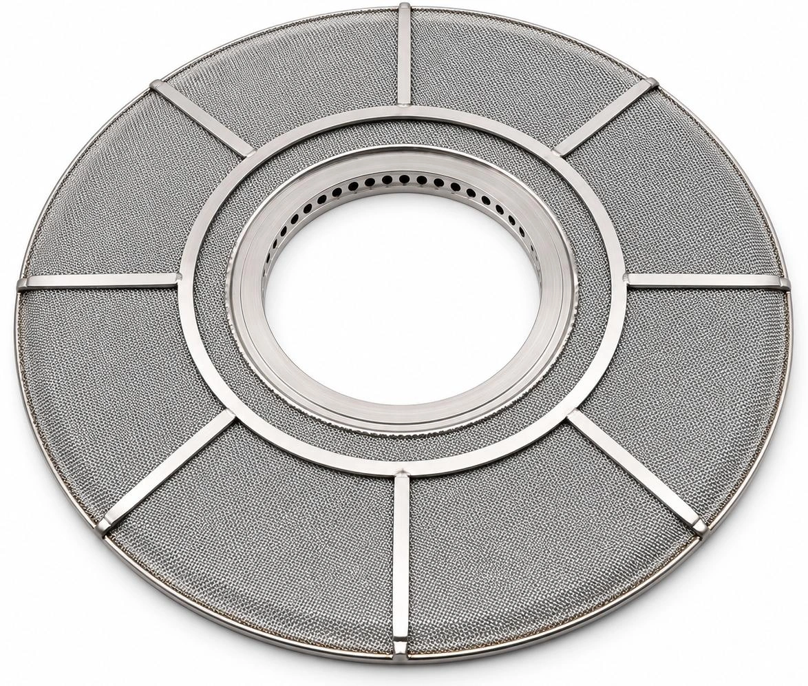
Application and Selection.
Disc spacing, edge sealing and hub fit support flow through the medium. Select the disc and the complete stack together for the polymer, throughput and required film quality.
- Flow path
- Through each face, then radially inward to the hub
- Published grades
- 5–100 μm at βx ≥ 75; confirm test basis
- Dimensions
- Outside diameter D, centre bore d and defined height H
Published pressure, temperature and viscosity limits are separate catalogue values. The approved drawing and specification define the permitted operating conditions.
Technical Information
Open a section to view the details, tables and illustrations.
Construction & Operating Principle
How Melt Passes through the Disc
The pressure difference between the unfiltered melt in the housing and the filtered melt in the central collector drives flow through both faces of each disc. The diagram shows one radial half section, from the sealed outer edge to the central hub.
How a Leaf Disc Filter Works
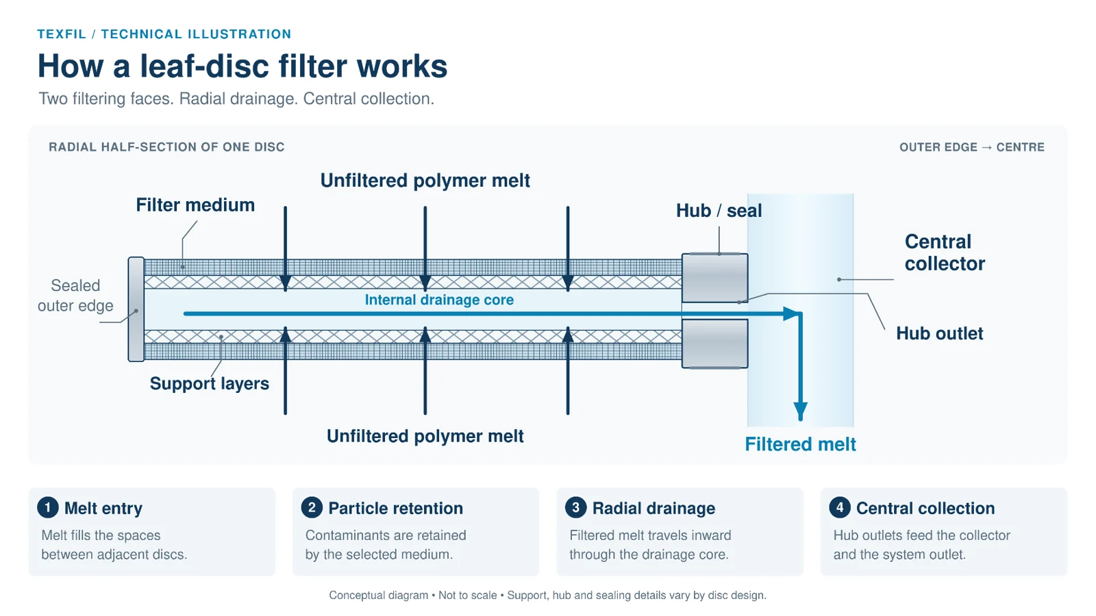
Two Filtering Faces ● Radial Drainage ● Central Collection
Conceptual flow illustration; the approved component drawing defines the actual construction.
Melt Entry. Unfiltered polymer fills the spaces between adjacent discs and contacts the upper and lower filtering faces.
Filtration. Melt passes through the porous medium on each face. The selected medium retains contaminants; the supporting layers maintain the filtering structure.
Radial Drainage. After passing through the medium, the filtered melt enters the internal drainage core and travels radially inward towards the hub.
Central Collection. Melt passes through the hub outlets into the common collector, which carries the combined flow from the disc stack to the system outlet.
Why Sealing and Spacing Matter
The sealed outer edge and hub interface prevent melt from bypassing the medium. Correct inter disc spacing maintains access to both faces and supports consistent flow distribution.
Technical Specifications
Published Range and Rating Basis
Confirm applicability to the selected medium, disc construction and assembled stack before ordering.
Parameter | Published Limit |
|---|---|
Working Pressure | ≤ 31.7 MPa (317 bar) |
Working Temperature | ≤ 300°C |
Medium Viscosity | ≤ 260 Pa·s |
Differential Pressure | ≤ 10 MPa (100 bar) |
Filtration Grades
5, 7, 10, 15, 20, 25, 30, 40, 60, 80 and 100 µm at βx ≥ 75
What βx ≥ 75 Means
The beta ratio compares upstream and downstream particle counts at or above size x. A ratio of 75 corresponds to approximately 98.67% removal under the applicable particle count test conditions.
Efficiency (%) = 100 × (1 − 1 / βx)
At βx = 75: 100 × (74 / 75) ≈ 98.67%
Request the test method, fluid, challenge particles and operating conditions for the quoted grade. The catalogue does not identify that test protocol.
A particle beta rating alone does not establish removal of deformable gels in a hot polymer melt.
Working Pressure and Differential Pressure
Working pressure concerns the pressurised process. Differential pressure is the pressure difference across the filter.
The published maxima are separate limits; they do not establish a combined operating envelope or a change out set point.
Specify normal and peak pressures, temperature, viscosity at the relevant shear conditions, start up transients and the approved terminal differential pressure.
Dimension Guide
Understanding D, d and H
Use these three dimensions to identify the basic disc envelope and centre opening. The plan view shows the disc face; the section shows the centre bore and axial height.
Leaf Disc Dimensions Explained
Outside Diameter ● Centre Bore ● Catalogue Height
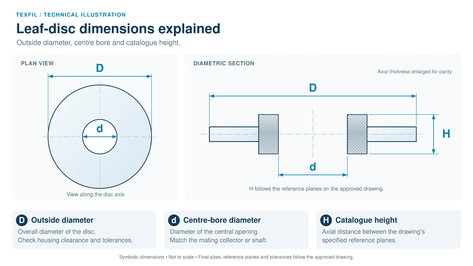
Schematic geometry; axial thickness is enlarged for clarity. Dimensions are not to scale.
D - Outside Diameter. The overall diameter measured across the outer edge of the disc. Confirm the required clearance to the filter housing.
d - Centre Bore Diameter. The diameter of the central opening. Confirm fit and tolerances with the mating collector or shaft.
H - Catalogue Height. The axial distance between the reference planes specified for that design. Confirm whether the drawing measures across the hub, seal faces or another defined feature.
Drawing Check Before Ordering
State all dimensions in millimetres and confirm the current component drawing. H should not be assumed to equal the filter medium thickness or the assembled stack pitch.
Configurations & Dimensions
Selected Catalogue References
Group numbers identify the catalogue sets; they are reference labels, not hub classifications.
Set | Source Reference | D mm | d mm | H mm | AREA m² |
|---|---|---|---|---|---|
1 | Ftd - R | 304.8 | 85 | 6.5 | 0.12 |
1 | Ftd - S/233 / 234 | 304.8 | 63.5 | 6.5 | 0.13 |
1 | Ftd - 133 | 254 | 85 | 6.5 | 0.08 |
1 | Ftd - 179 / 179a / 179B / 179F | 177.8 | 47.6 | 6.5 | 0.04 |
1 | Ftd - 224 / 224a | 152.4 | 38.2 | 6.5 | 0.032 |
1 | Ftd - 266 | 177.8 | 85 | 6.5 | 0.029 |
2 | Ftd - P / J | 177.8 | 47.6 | 6 | 0.04 |
2 | Ftd - 167 | 304.8 | 63.5 | 5.5 | 0.13 |
3 | Ftd - 164 / 164a / 164B / 164C | 177.8 | 47.6 | 10.5 | 0.04 |
3 | Ftd - 248C | 304.8 | 63.5 | 6.1 | 0.13 |
3 | Ftd - 256 | 177.8 | 47.4 | 7.7 | 0.05 |
3 | Ftd - 257 | 304.8 | 63.9 | 7.7 | 0.14 |
FTD identifiers are retained for catalogue cross reference. Area values are as published. Confirm current drawings, tolerances and the effective area of the supplied component.
Media, Hubs & Stack Sizing
Select the Complete Filtration Assembly
Available Constructions
MEDIA: sintered stainless steel fibre, multilayer sintered stainless steel wire mesh, or sintered metal powder. Hub options: welded centre ring (hard hub) and centre ring (soft hub).
SINTERED FIBRE. A porous bonded fibre structure can provide depth capture. Assess the balance of contaminant capacity, retention and clean resistance for the polymer.
SINTERED MESH. Woven layers offer a defined filtration structure with supporting layers. Review the weave and full laminate, especially where hard particle contamination dominates.
SINTERED POWDER. A porous matrix of bonded particles provides another route for gel sensitive duties. Compare tested performance and resistance; media names alone do not establish equivalence
Filter Area and Surface Loading
Use the confirmed active area per disc when sizing a stack. A simple accounting example illustrates the calculation; it is not a throughput recommendation.
Illustrative Input | Value |
|---|---|
Number of Active Discs | 40 |
Assumed Active Area per Disc | 0.12 m² |
Assumed Mass Throughput | 1,200 kg/h |
Total Area = 40 × 0.12 = 4.8 m²
Mass Loading = 1,200 / 4.8 = 250 kg/(m²·h)
Count each disc’s confirmed total area once. Include any excluded end faces, seals or inactive zones in the supplier’s area definition. Stack count alone does not determine hydraulic capacity.
Verify the Hydraulics
Request pressure loss data for the actual polymer, temperature, throughput and complete stack. The review should include the media, internal drainage, inter disc spaces, collector and housing.
Application, Cleaning & Service
Build the Specification Around Film Quality
Leaf disc selection should address the film’s defect limits, polymer behaviour and operating economics. Flow distribution, pressure loss and gel control should be assessed together.
Polymer and Production Duty. State resin family and grade, virgin/recycled blend, additives, melt temperature, viscosity basis, throughput range and the product being made.
Contamination and Quality Target. Describe hard particles, degraded polymer, gels and catalyst residues. Supply retained contaminant samples or microscopy where available, and define the accepted film defect measure.
Existing Assembly. Provide the OEM or housing reference, disc drawing and revision, current medium and grade, hub type, seal details, disc count, spacers, stack height and change out history.
Trial and Performance Review
Compare candidate assemblies at matched melt conditions. Record initial differential pressure, its rise with time or tonnes processed, run length, film defects, breaks and off spec output. Include pressure transients and the reason for each change out in the trial record.
Cleaning and Return to Service
Use a cleaning sequence qualified for the polymer deposits, media, hub and weld construction. Following cleaning, evaluate flow resistance and integrity against an approved baseline and acceptance criteria for that filter design.
Visual cleanliness alone does not demonstrate restored filtration performance. Keep an individual record of service cycles, cleaning history, inspection results and test disposition; retire damaged discs or those outside the agreed criteria.
Enquiry and Acceptance
Send the drawing, current filter sample details, polymer duty, required grade and quantity.
Agree material certification, dimensional inspection, sealing checks, performance evidence and packaging before finalising supply.
Prepare Your Enquiry
What to Send Us.
Disc and stack drawings; hub design; D, d and H; disc count; polymer; throughput; temperature; line and differential pressures.
Discuss this product