
Application and Selection.
A spin pack filters and distributes the melt before the spinneret. Correct layer sequence, support and sealing help control flow and prevent bypass.
- Scope
- Pack bodies, screen packs, seals and internal components
- Media options
- Woven mesh, sintered media and graded powder beds
- Selection basis
- Approved pack drawing and process duty
Technical Information
Open a section to view the details, tables and illustrations.
Product Overview
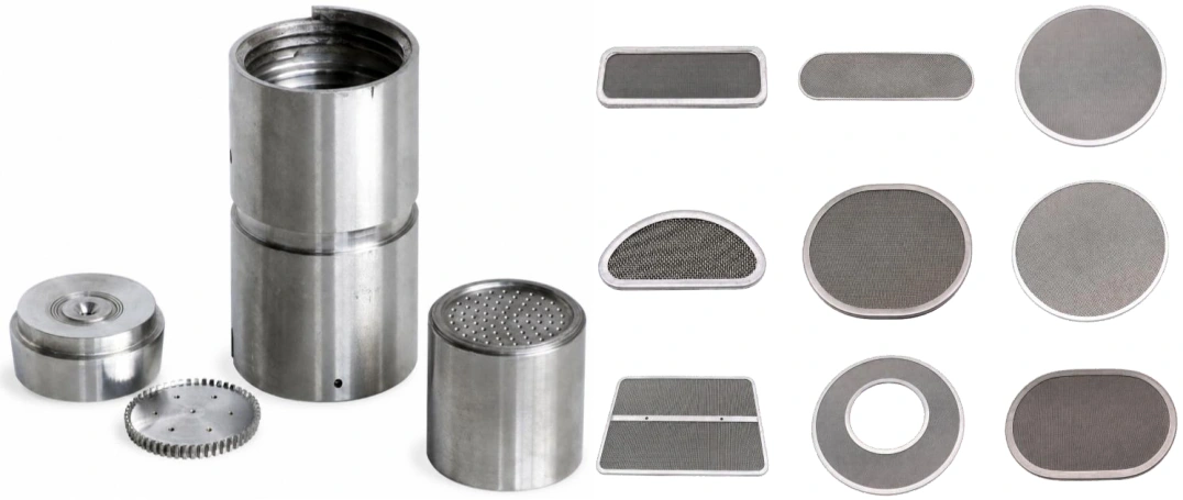
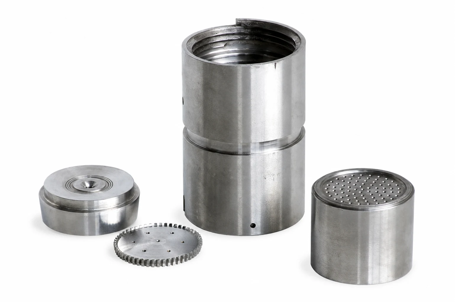
Representative spin pack bodies and precision internal components
Engineered to Support
Controlled melt cleanliness, reliable sealing, stable pressure development and consistent distribution to the spinneret or extrusion die.
TYPICAL POLYMERS: PET ● rPET ● PA6 ● PA66 ● PP ● PE ● SPECIALITY POLYMERS
Technical Selection
Pack body, filter geometry, media, layer stack and sealing interface are selected from the approved drawing and actual process data.
Spin Pack Bodies
Precision Housings for Filtration, Distribution and Extrusion
Custom circular and rectangular configurations can be engineered to match the spinning beam, spinneret, sealing method and validated process duty.
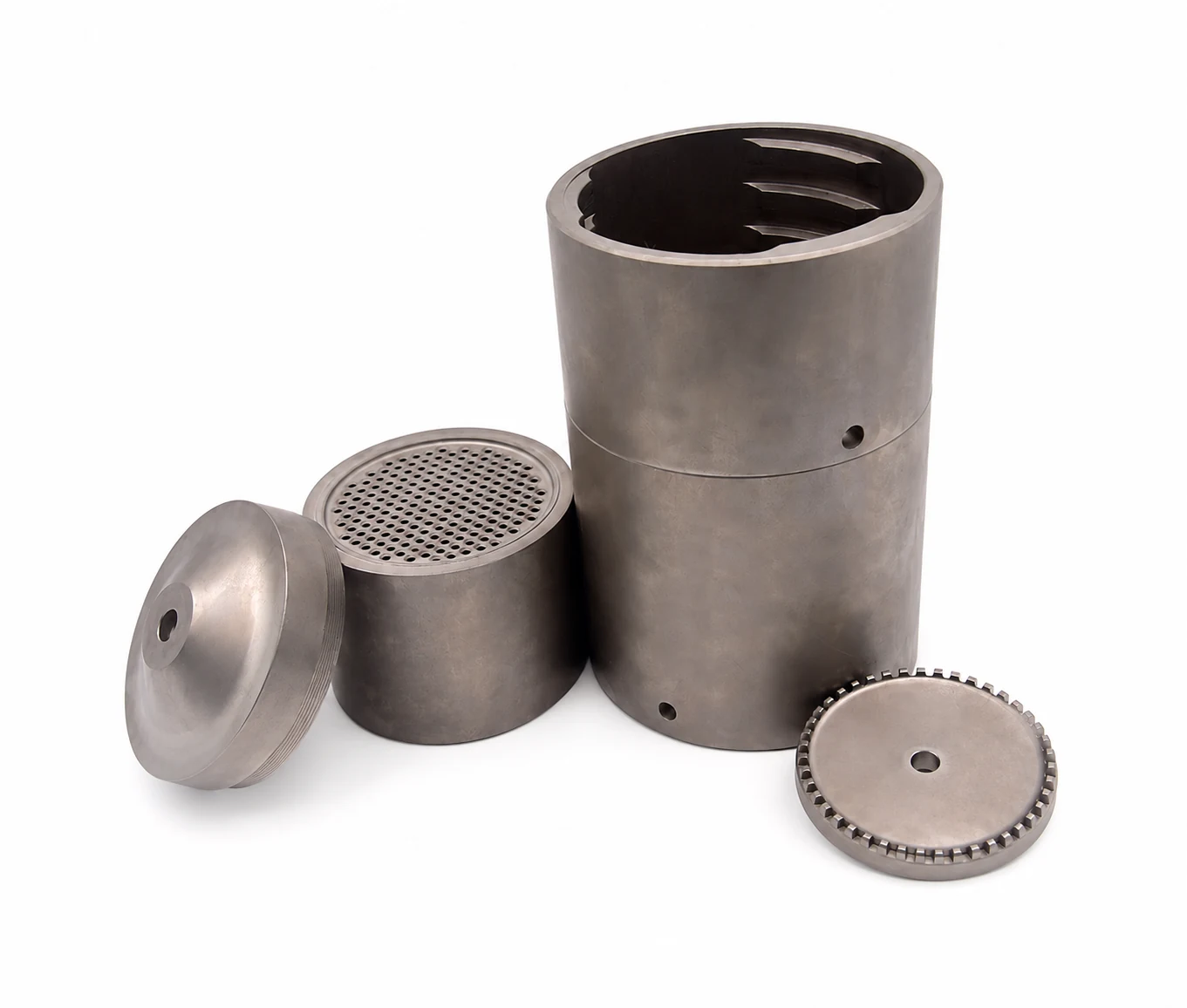
Representative circular spin pack body components
Application Scope
01 SYNETHETCI FILAMENT: Pack interfaces for textile and industrial filament spinning
02 STAPLE FILAMENT: Housing and internal stack configurations for stable multi hole extrusion.
03 POLYMER PROCESSING: Screen pack and filtration duties requiring accurate location, sealing and support.
04 CUSTOM REPLACEMENT: Dimensional reproduction from an approved drawing or verified sample; the governing OEM limits must be retained
Spin Pack Engineering
Reliable Spinning Depends on Five Controlled Design Priorities
Every replacement or custom pack should be reviewed as a pressure containing, heated precision assembly - not only as a machined component.
01 DIMENSIONAL ACCURACY: Critical diameters, threads, shoulders, plate location and spinneret seating must reproduce the approved interface.
02 PRESSURE AND TEMPERATURE CAPABILITY: Body alloy, wall section, closure and fasteners must suit the validated operating envelope.
03 SEALING INTEGRITY: Mating faces and sealing elements must limit polymer bypass and external melt leakage.
04 CONTROLLED FLOW PATH: Internal transitions should distribute melt without unnecessary stagnation, dead zones or excessive residence time.
05 SERVICEABILITY: The assembly should support repeatable opening, cleaning, inspection and rebuilding without damage to precision surfaces
Engineering Review Points
Interface | Evidence Required |
|---|---|
Spinning Beam | Approved cavity, feed, mounting and sealing dimensions. |
Internal Stack | Filter, loose media, screens, breaker/distribution plates and spinneret drawing. |
Operating Duty | Polymer, throughput, temperature, pressure profile, cleaning and change cycle. |
Design Authority
The approved drawing, validated material specification and process limits govern the final supplied construction.
Configuration
Match the Complete Spinning Beam and Spinneret Interface
Mounting, melt feed, body form, closure and sealing are interdependent. A dimensional match alone does not confirm process suitability.
Configuration Point | Typical Alternatives | Selection Basis |
|---|---|---|
Installation | Top mounted or bottom mounted | Pack weight, access and spinning box design. |
Melt Feed | Top feed or side feed | Existing melt route and inlet sealing interface. |
Body Form | Circular, rectangular or custom | Spinneret size, cavity dimensions and product duty. |
Closure | Threaded, bolted, clamped or quick lock | Approved OEM interface and validated pressure / temperature limits. |
Sealing | Metallic or application specific seal | Polymer chemistry, temperature, surface finish and compression geometry. |
OEM Compatibility
Barmag, Neumag, TMT and other OEM packs may combine or reposition screens, filters and distribution plates. Supply should be based on the approved pack drawing or verified assembly; no OEM affiliation is implied.
Functional Melt Path
The Pack Creates the Controlled Pressure Path to the Spinneret
A representative pack routes metered polymer through the sealed housing, filtration and distribution stack before filament formation. Exact sequencing remains application and OEM specific.
01 Metered MeltFrom the spinning pump | 02 Sealed HousingContains the hot melt | 03 FiltrationScreens / graded media | 04 DistributionBreaker or support plate | 05 SpinneretStable capillary feed |
|---|
Representative Loose Media Arrangement
Direction of Melt Flow | Typical Element | Purpose |
|---|---|---|
1 | Retaining Mesh / Protective Screen | Contains loose metallic media and protects the bed. |
2 | Coarse Grade | Provides open upstream capacity and stages contaminant loading. |
3 | Medium Grade | Progressively increases resistance and retention. |
4 | Fine Grade | Provides the final selected retention before downstream support. |
5 | Retaining Mesh and Support Screens | Prevents media migration and transfer’s load. |
6 | Breaker / Distribution Plate | Supports the stack and distributes flow to the spinneret. |
Graded Bed Principle
Where a graded powder bed is used, coarse to medium to fine staging in the melt flow direction can delay local blockage and progressively build filtration resistance. Particle grades, quantities and bed depths must be selected for the actual polymer, viscosity, melt cleanliness, temperature and throughput.
Residence Time
Avoid unnecessary internal volume and stagnation after filtration. Excess residence time can aggravate thermal degradation and create new contamination downstream of the filter.
Filters for Polymer Extrusion
Final Protection Before the Spinneret or Extrusion Die
Custom flat, pleated and shaped metallic filters can be configured for controlled melt cleanliness, flow distribution and protection of fine downstream geometry.
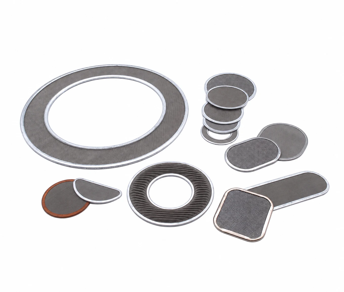
Representative flat, annular and shaped metallic filter assemblies
Typical Polymer & Process Scope
Polymers | Extrusion Duties |
|---|---|
PET and rPET | Textile filament, industrial filament, staple fibre and selected nonwoven processes. |
PA6 and PA66 | Filament and other precision melt extrusion duties. |
PP and PE | Fibre, nonwoven, film or other process compatible filtration duties. |
Specialty Polymers | Subject to confirmed alloy, seal, temperature, viscosity and cleaning compatibility. |
Selection Basis
The filter is engineered around the contaminant profile, viscosity, throughput, temperature, available area, clean pressure drop, terminal pressure and target on stream life.
Filtration Objectives
Cleaner Melt, Protected Capillaries & Controlled Hydraulic Resistance
The filter and its support stack should provide retention without creating unacceptable pressure loss, dead volume, deformation or bypass.
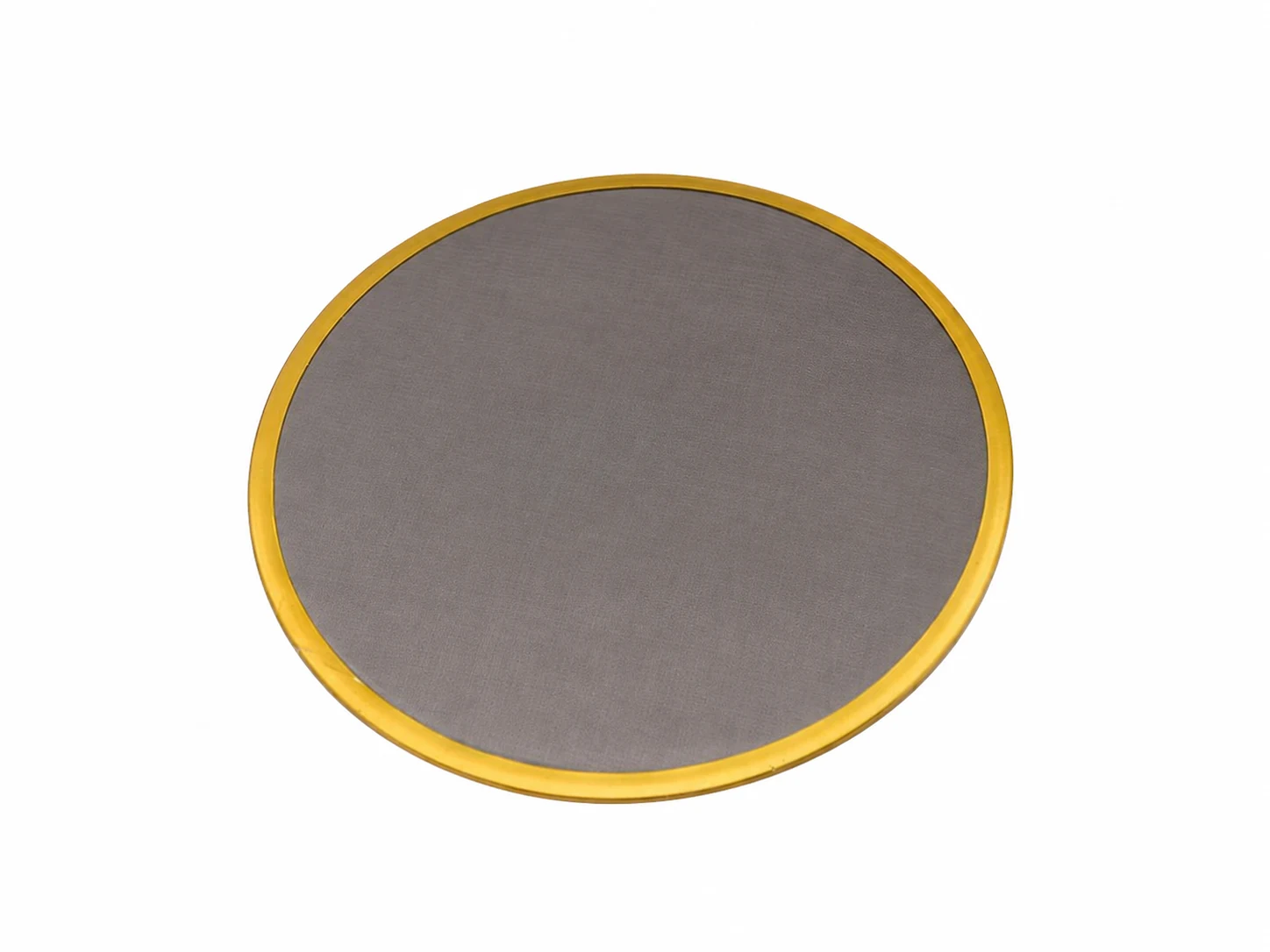
Flat metallic filter with prepared edge ring
Qualification Rule
Retention rating, permeability, support structure and sealing must be validated as a complete assembly. A mesh number alone is not a filter specification.
01 REMOVE CONTAMINATION: Retain hard particles, oxides, carbonised material, agglomerates and, when a suitable depth medium is used, deformable gel type contamination.
02 PROTECT DOWNSTREAM GEOMETRY: Reduce the risk of contamination reaching spinneret capillaries, film dies and other critical flow passages.
03 CONDITION MELT FLOW: Add controlled resistance that supports distribution and mixing without excessive clean pressure drop.
04 SUPPORT PACK LIFE: Provide sufficient area and dirt holding capacity to manage pressure rise rate across the operating cycle.
Filter Geometry
Match the Pack Cavity & Available Filtration Area
Geometry affects effective area, face velocity, initial pressure drop, dirt capacity and mechanical support. The approved pack dimensions remain the design boundary.
| 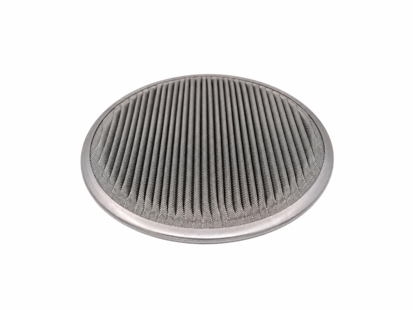 | 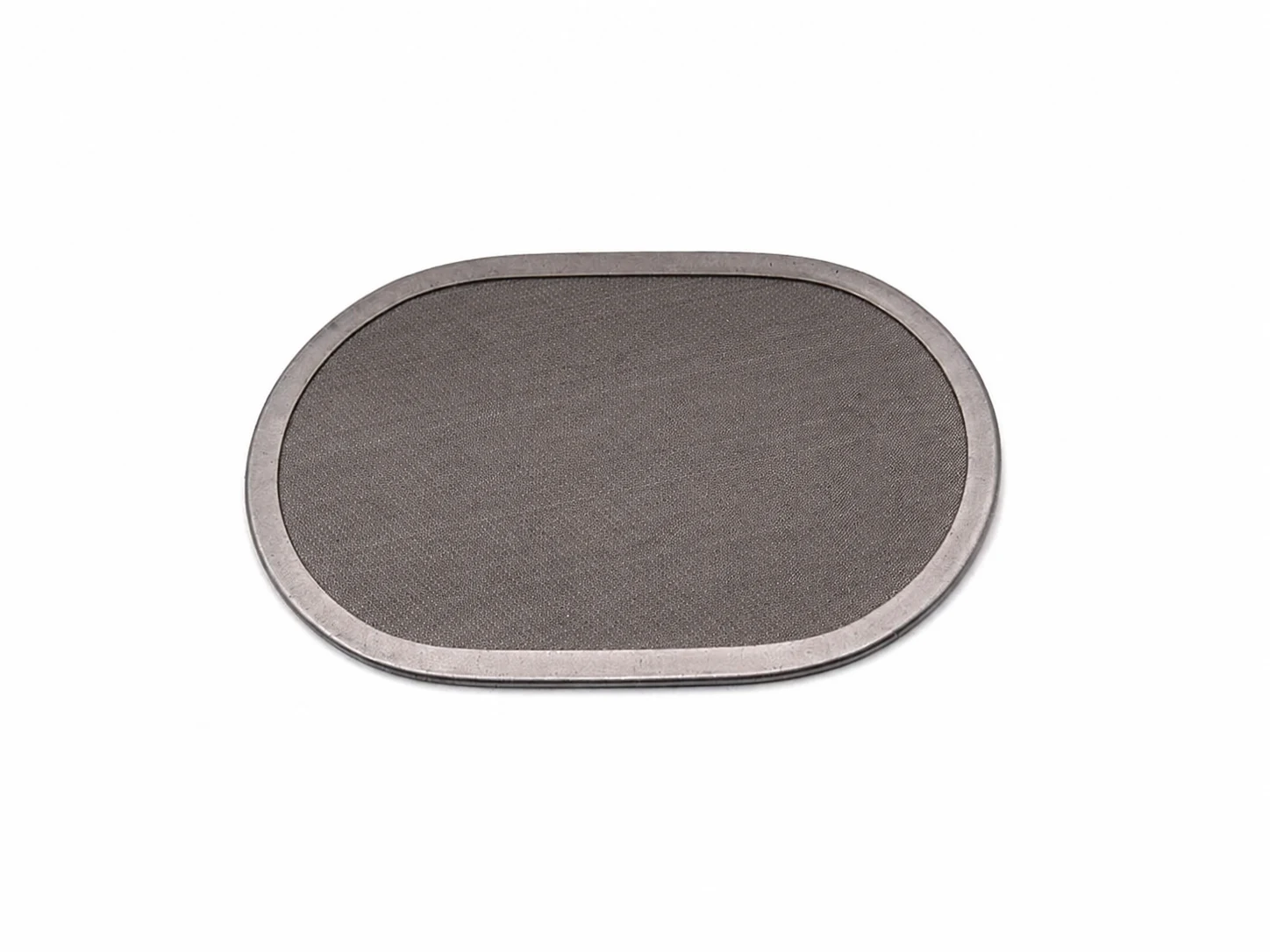 |
Flat FiltersCompact and economical where pack depth is limited and contaminant loading is controlled. | Pleated FiltersExpanded area can lower face velocity, reduce initial pressure drop or extend on stream life. | Shaped FiltersRound, annular, rectangular, semicircular, oval and application specific profiles can match existing cavities. |
Dimensional Control
Control Point | Confirm Before Manufacture |
|---|---|
Envelope | Overall profile, outside dimensions, thickness and available cavity depth. |
Sealing | Rim material, compression land, surface treatment and bypass control feature. |
Layer Stack | Media grade, support layers, orientation, count and joining method. |
Flow Direction | Upstream/downstream orientation and support against differential pressure. |
Manufacturing Basis
Do not manufacture from a product photograph alone. Use an approved drawing or dimensionally verified reference sample.
Media Selection
Choose for the Contaminant Mechanism - Not Only the Mesh Number
Filtration medium, support structure and rating method should be considered together. Sintered metal fibre media can provide high porosity and dirt holding capacity for demanding viscous polymer duties.
Medium | Filtration Behaviour | Best Fit Considerations |
|---|---|---|
Woven Wire Mesh | Primarily surface filtration with defined openings and good permeability. | Hard particulate, lower contaminant loading, cleanability and robust support. |
Dutch Weave Mesh | Dense woven path for finer retention with mechanical strength. | Tighter retention; support and permissible differential pressure remain critical. |
Sintered Metal Fibre | Three dimensional depth filtration through a tortuous porous structure. | Broad contaminant load, deformable gels, high dirt holding need and stable high temperature service. |
Supported Composite | Fine filtration layer combined with drainage and structural support. | Application specific balance of retention, permeability, support and cleanability. |
Rating Must Be Stated Clearly
Identify whether the value is nominal or absolute and name the test method or acceptance basis.
Confirm media construction, wire/fibre alloy, support layers and intended flow direction.
Evaluate clean pressure drop and pressure rise rate at representative polymer viscosity and throughput.
Confirm resistance to collapse, deformation, edge bypass and cleaning damage.
Commercial Caution
Two products described by the same nominal micron value may have different pore distributions, permeability, dirt capacity and pressure behaviour.
Layer Construction
Support, Sealing & Joining Control Filter Stability
The layer stack must remain located and supported under temperature, differential pressure, handling and - where approved - cleaning cycles.
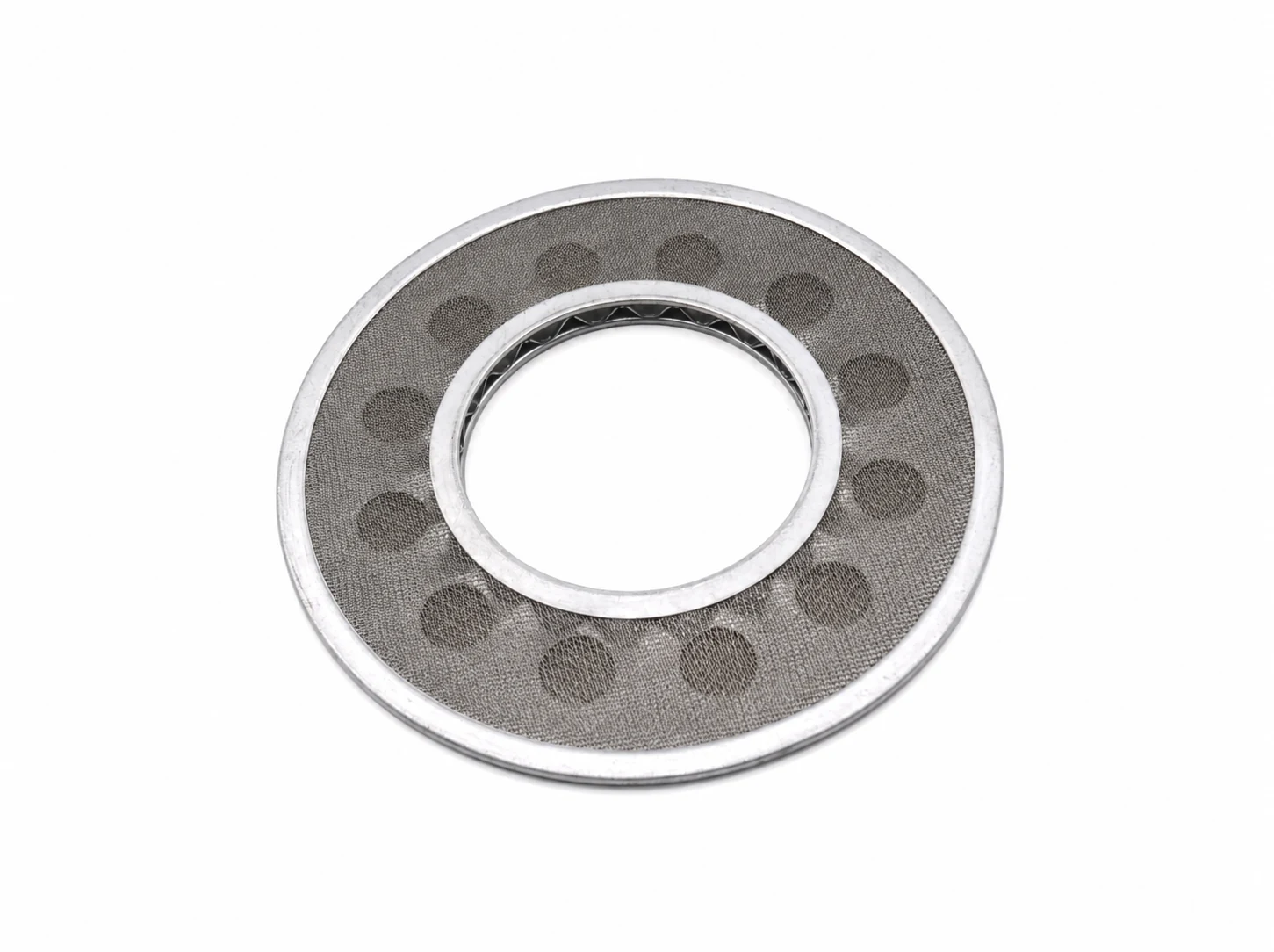
Representative annular metallic filter assembly
Stage | Typical Custom Assembly Control |
|---|---|
01 | Filter and support layers are cut or stamped to the approved profile. |
02 | Media are assembled in the defined sequence and flow orientation. |
03 | Fine media are mechanically supported against the validated differential pressure. |
04 | The stack is located in the prepared edge ring or sealing feature. |
05 | The assembly is pressed, welded or otherwise joined to maintain integrity. |
06 | Dimensions, layer count, flatness and visual condition are verified. |
Common Edge and Surface Options
Stainless Steel ● Aluminium ● Copper ● Application Specific Sealing Materials
Nickel Plated Copper ● Anodised Aluminium ● Untreated Stainless Steel
Compatibility
Final alloy, coating and sealing materials must be confirmed for polymer chemistry, temperature, cleaning method and any product purity requirement.
Effect on Filament Quality
Filtration Supports Uniform Spinning but It Is One Part of the Quality System
Pack filtration can reduce contamination related breaks and off denier variation, but it cannot correct polymer degradation, poor metering, temperature, quench, spinneret, draw or winding faults. Tenacity and elongation are therefore mainly indirect effects.
Quality Parameter | Filtration / Pack Influence | Interpretation |
|---|---|---|
Linear Density & Denier Evenness | Uniform pressure and distribution help maintain comparable flow to each spinneret capillary; fouling, bypass or maldistribution can produce off denier yarn. | Direct process support effect, provided metering and take up remain stable. |
Filament Evenness & Cross Section | Cleaner capillaries and balanced flow reduce hole to hole disturbances and irregular filament formation. | Direct support; spinneret condition and quench symmetry also matter. |
Tenacity | Removal of hard particles, gels and char reduces weak points and broken filaments; excessive residence time can negate this benefit through degradation. | Mainly indirect. Draw ratio, orientation, crystallisation and polymer quality dominate. |
Elongation | Stable melt and fewer defects can reduce variability, but filtration does not set the molecular orientation. | Mainly indirect. Draw/winding conditions are primary controls. |
Break Rate / Missing Filaments | Contaminant retention protects fine capillaries and reduces plug related interruptions. | Strong direct relationship when contamination is the root cause. |
Appearance & Defect Count | Improved removal of char, oxides, agglomerates and gels can reduce visible defects and deposits. | Direct for retained contamination; colour and degradation can have other causes. |
Process Stability | Sufficient area and controlled resistance moderate pressure rise rate and extend the usable pack cycle. | Direct hydraulic effect; monitor differential pressure and throughput together. |
Selection Inputs
Balance Retention, Pressure Drop & Pack Life
Reliable selection requires process, contamination, hydraulic and dimensional data. Maximising one attribute in isolation usually compromises another.
Information Category | Data Required for Technical Review |
|---|---|
Polymer | Grade, virgin/recycled content, additives, intrinsic viscosity or melt viscosity range and thermal sensitivity. |
Process Duty | Filament, fibre, nonwoven, film, pellet or other extrusion service. |
Operating Conditions | Normal/maximum melt temperature, viscosity, total throughput, throughput per pack and operating cycle. |
Contamination | Hard particles, gels, char, oxides, agglomerates, target defect and current quality issue. |
Filtration Requirement | Current/required rating, rating method, media type, effective area and quality objective. |
Pressure Profile | Clean inlet/outlet pressure, initial differential pressure, terminal limit and pressure rise rate. |
Pack Geometry | Cavity, filter dimensions, available depth, flow direction, rim and sealing method. |
Life & Cleaning | Current change frequency, target pack life, cleaning method, reuse count and post cleaning test. |
Optimisation Target
Successful design balances retention, acceptable clean pressure drop, controlled pressure rise rate and useful on stream life.
Reference Evidence
Provide the existing approved drawing, a verified sample, photographs, nameplate information and current product specification wherever available.
Plant Qualification
Prove Performance Against Agreed Process & Yarn Quality Criteria
A controlled comparison with the existing approved pack/filter provides the most reliable basis for routine supply approval.
Trial Measurement | What to Record | Decision Value |
|---|---|---|
Initial Pressure Drop | Stable throughput, melt temperature and viscosity after start up. | Confirms permeability and hydraulic fit. |
Pressure Rise Rate | Differential pressure trend over the agreed operating period. | Indicates contaminant loading and usable pack life. |
Process Stability | Throughput, melt temperature, pressure fluctuations and interruptions. | Checks that the assembly supports normal operation. |
Filament Quality | Linear density CV, tenacity and elongation with CV, breaks, missing filaments and visual defects. | Links pack performance to saleable quality. |
Pack Condition | Screens, plates, seals, retained contamination, deformation and evidence of bypass after removal. | Confirms mechanical suitability and failure mode. |
Cleaning Recovery | Post cleaning permeability, integrity result and pressure drop recovery. | Determines whether repeated use remains economical and safe. |
Recommended Approval Sequence
01 APPROVE THE DESIGN: Confirm drawing, media description, rating method, materials, dimensions and operating limits.
02 DEFINE THE TRIAL: Agree quantity, baseline, operating window, monitoring frequency and terminal differential pressure.
03 RUN COMPARABLE CONDITIONS: Use the same polymer grade and stable process settings where practical.
04 REVIEW TOTAL PERFORMANCE: Assess yarn quality, pressure trend, pack life and total operating cost before routine approval.
TEXFIL Application Support
Application Led Support from Enquiry to Controlled Supply
TEXFIL coordinates application review, drawing confirmation, sample qualification, plant trial planning, commercial support and scheduled supply for polymer melt filtration projects.
01 Application DataProcess + quality need | 02 Drawing + MediaInterface confirmation | 03 Sample ApprovalDimensional review | 04 Controlled TrialProcess evidence | 05 Routine SupplyAgreed specification |
|---|
Configurable Project Basis
Control Point | Project Basis |
|---|---|
Pack Body & Interfaces | Mounting, melt feed, closure, sealing and spinneret interface to approved dimensions. |
Media & Rating | Woven mesh, Dutch weave, sintered metal fibre, graded powder or supported composite to an agreed rating basis. |
Internal Construction | Retaining screens, support layers, breaker/distribution plates and flow direction to the approved design. |
Materials & Seals | Alloy and sealing materials selected for polymer, temperature, pressure and cleaning method. |
Verification | Dimensional and visual inspection, with material, permeability or integrity records where specified. |
Documentation | Quotation, approved drawing, product specification and agreed inspection/test records. |
Representative Configuration
Individual Barmag, Neumag, TMT and other OEM packs may combine or reposition screens and distribution plates. The approved OEM drawing and validated process conditions govern the project.
Evidence Basis
Manufacturing location, certificates, test methods, inspection records and acceptance criteria are confirmed in the project quotation rather than implied by this brochure.
Prepare Your Enquiry
What to Send Us.
Pack drawing and revision; machine model; polymer; throughput per pack; screen and media arrangement; pressure profile; required quantity.
Discuss this product