
Application and Selection.
Choose the guide surface and geometry for the yarn path and operating position. The illustrated reference catalogue includes component photographs and dimensional drawings.
- Ceramic range
- Pins, eyelets, loops, inserts and profiled guides
- Assemblies
- Take up guides, traverse components and bi rotors
- Identification
- Machine position, mounting geometry and drawing
Some component references appear against more than one geometry in the brochure. Match the approved drawing and machine position before ordering.
Technical Information
Open a section to view the details, tables and illustrations.
Engineered for the Yarn Path
Application led component selection backed by textile process expertise.
Textile Process Knowledge Behind Every Enquiry
TEXFIL Technologies supplies technical components and support for extrusion and spinning lines. Our team brings more than 35 years of continuous synthetic filament industry experience across R&D, after sales, commissioning and production support.
01 Wear Resistant Contact 99.7% alumina ceramic for demanding yarn contact positions. | 02 Defined Guide Geometry Slots, radii, holes and mounting dimensions carried from technical drawings. |
|---|---|
03 Replacement Selection Complete take up assemblies and individual guide profiles for dimension based matching. | 04 Technical Support Selection based on machine, yarn, speed, existing part and operating position. |
35+ Years’ Experience ● Industry Led Support ● Global Customer Service
Selection Principle
Confirm the machine position, critical dimensions, yarn contact geometry and mounting arrangement before quotation or replacement.
Product Range
Ceramics, Take up Winder Guides & Bi Rotors
Engineered replacement components for consistent yarn contact and controlled transfer.
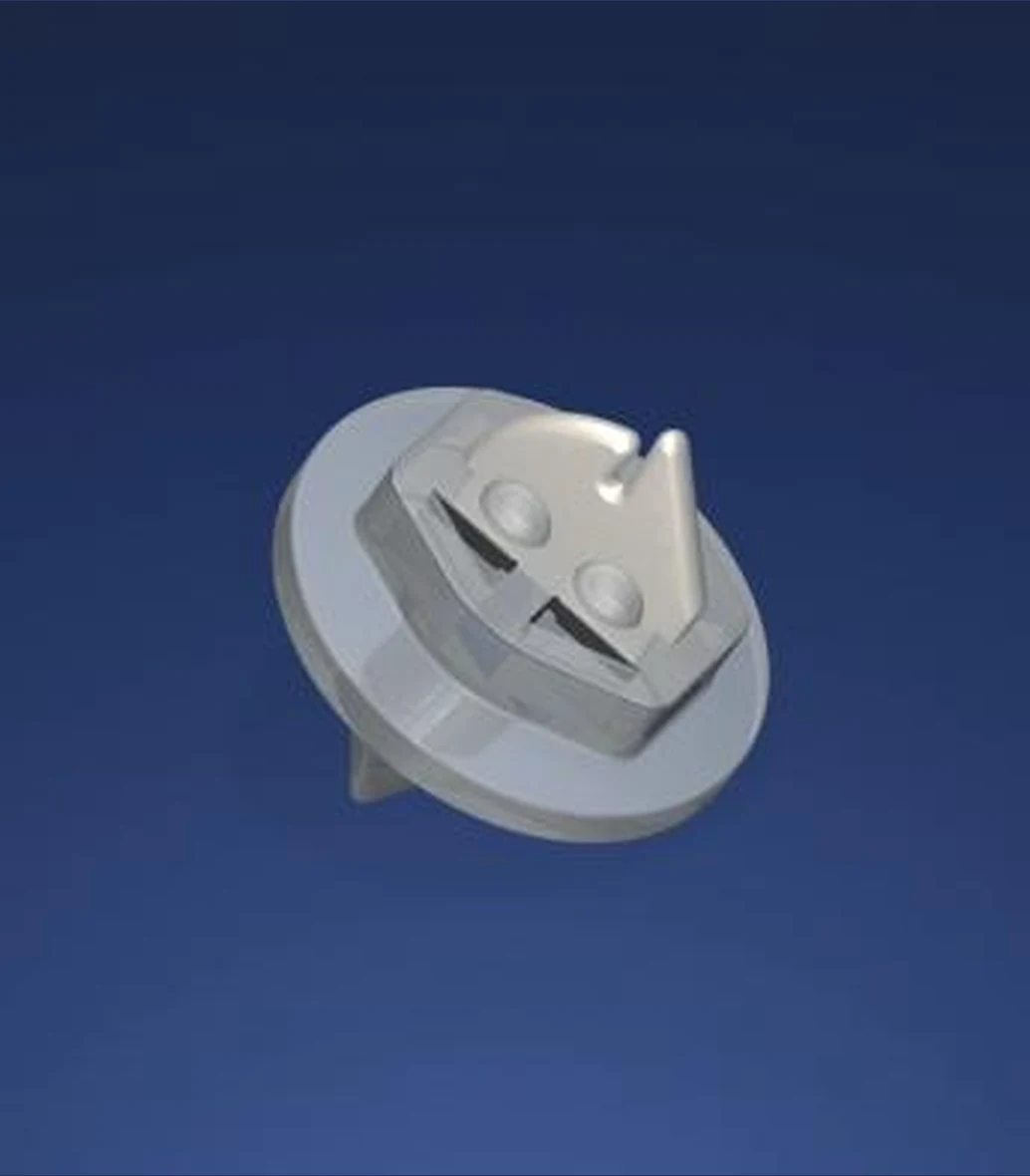
Take up AssembliesComplete Guide and Shoe Configurations. |  Ceramic InsertsPrecision 99.7% Alumina Thread Guides. |
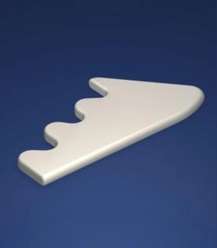 Profiled GuidesControlled Geometry for Defined Yarn Paths. | 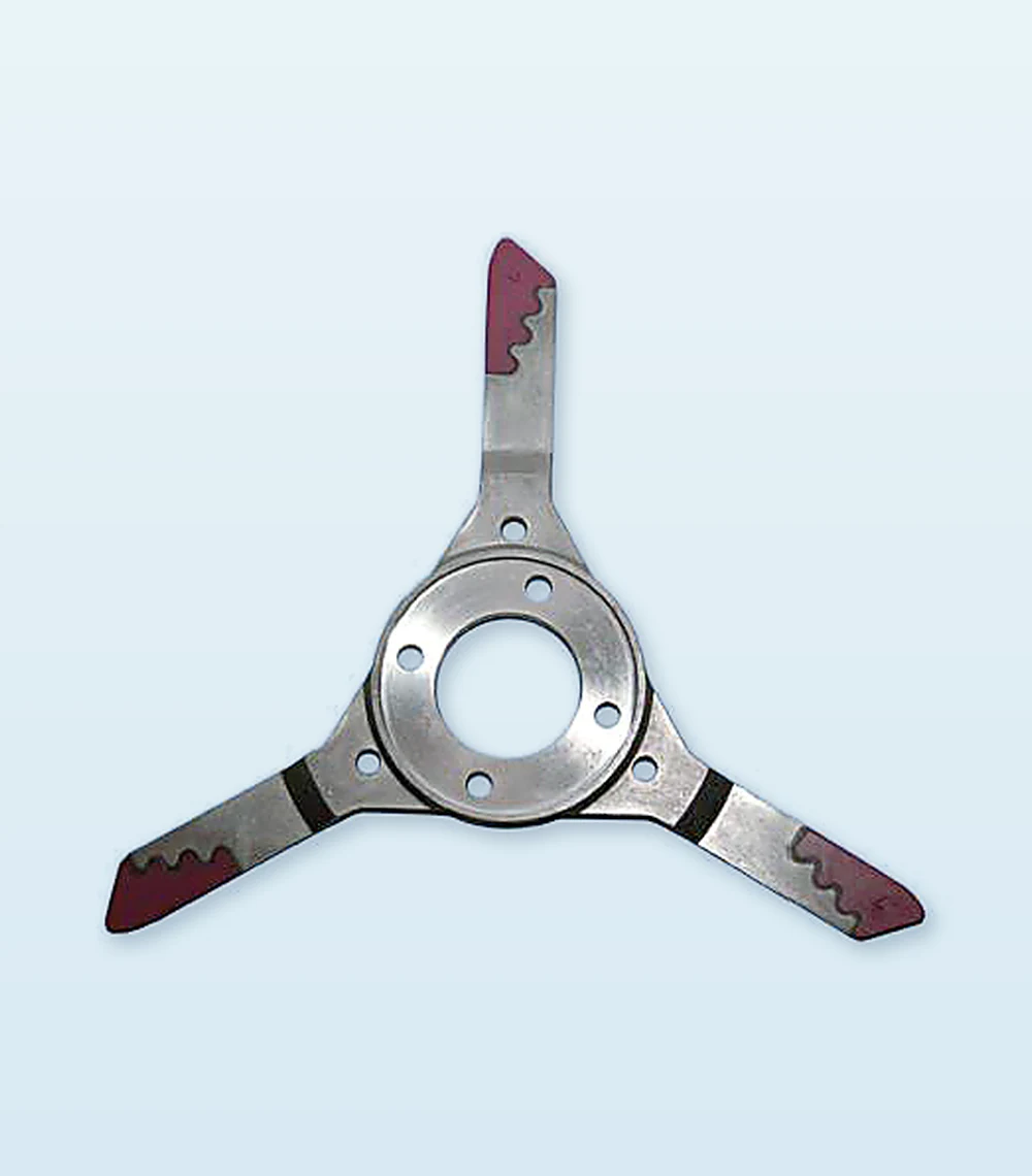 Bi - RotorsApplication Matched Traverse Wing Assemblies. |
Engineered for Consistent Yarn Contact
High purity alumina for reliable wear performance ● Controlled yarn contact geometry and smooth guide surfaces ● Replacement guides and rotor discs for selected take up winders.
Application Support
Product references support identification. Final selection should be confirmed from the existing part, drawing, sample and machine position.
Ceramic Yarn Guides
Precision 99.7% Alumina Guide Components
Yarn friendly guide pins and loop guides with controlled yarn contact geometry.
TF997-1109Barmag Ref. 555518/599.7% ALUMINA · Guide Pin · Ø4 × 20 |
TF997-1112Barmag Ref. 309620/599.7% ALUMINA · Guide Pin · Ø4 × 50 | ||||
TF997-1114Barmag Ref. 465241/099.7% ALUMINA · Guide Pin · Ø5 × 28 |
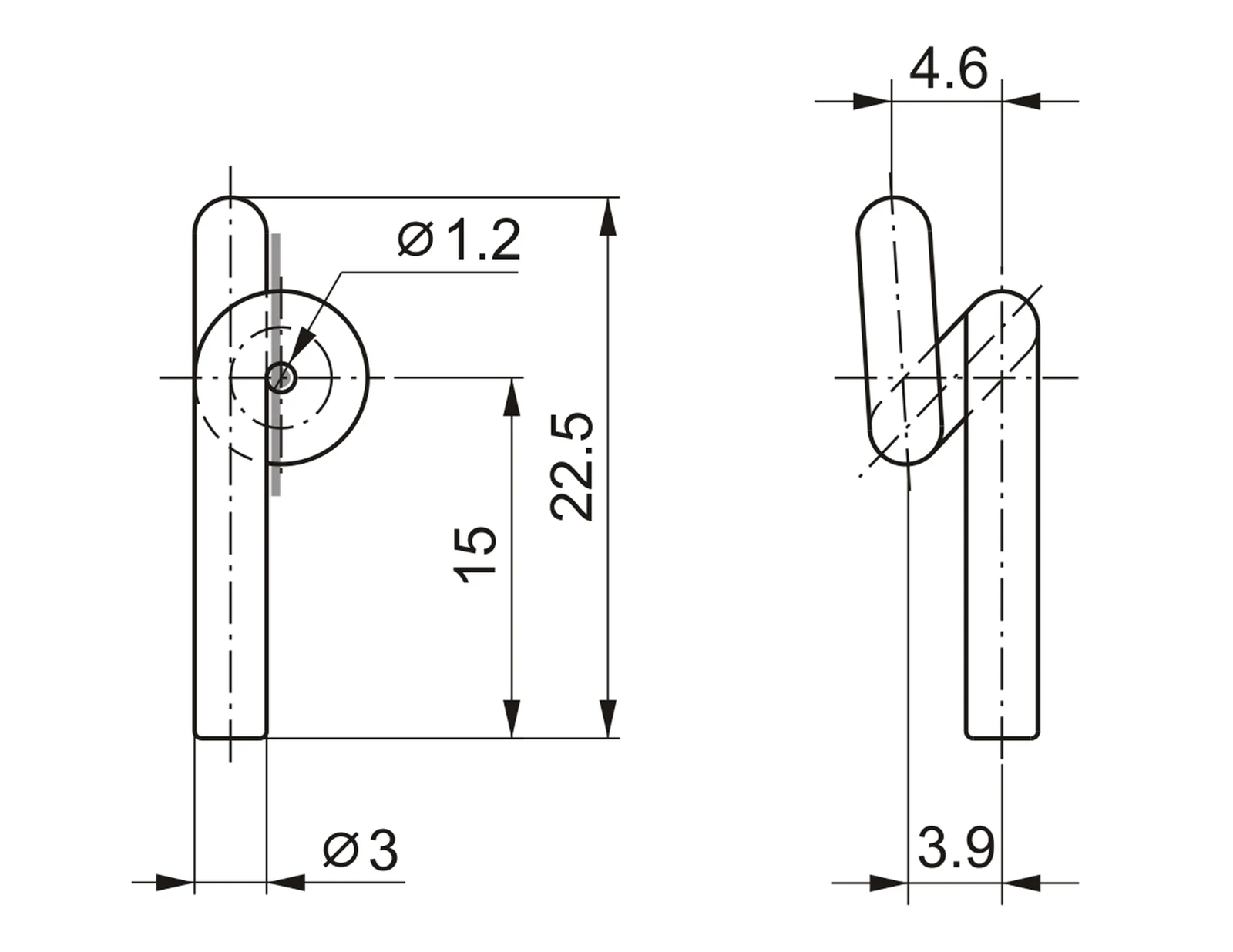
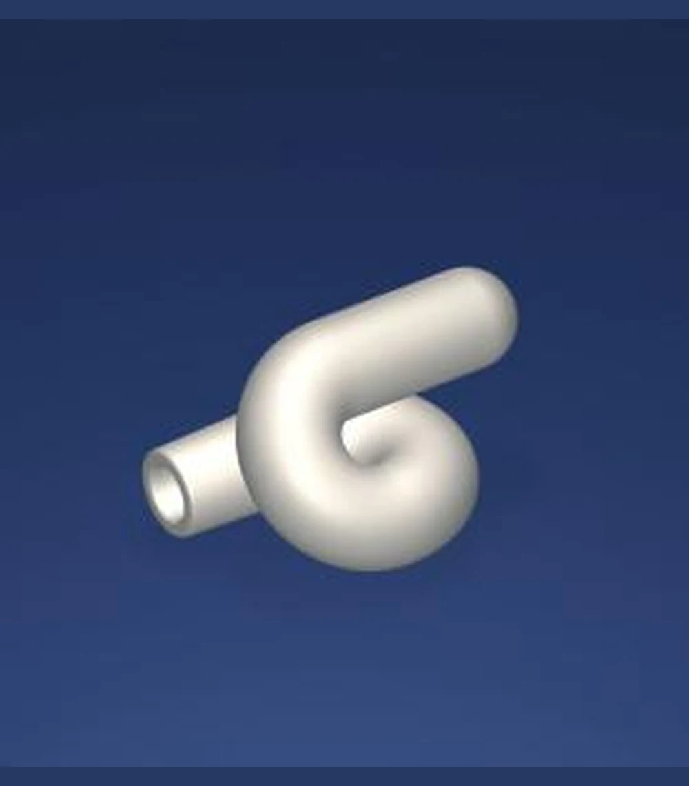
TF997-1244Barmag Ref. 083786/799.7% ALUMINA · Loop Guide · Ø3 × 22.5 |
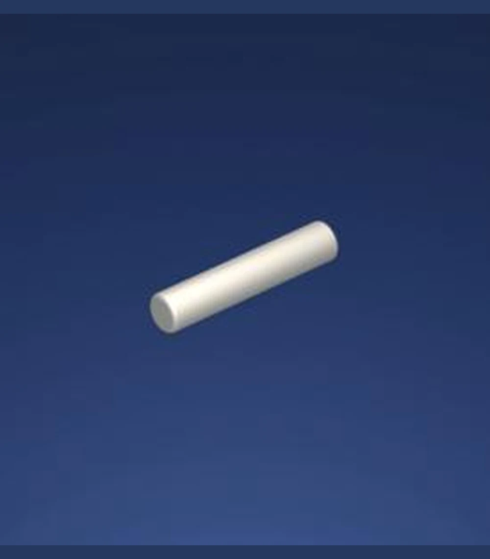
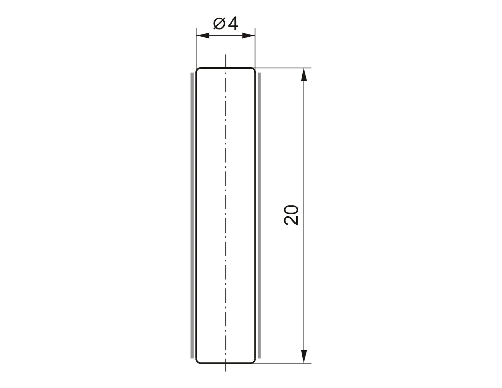
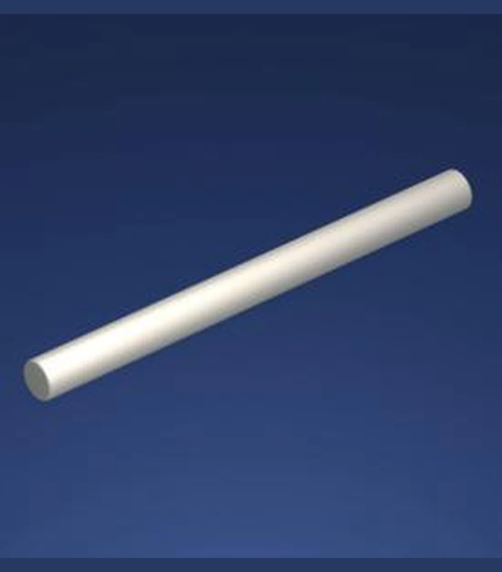
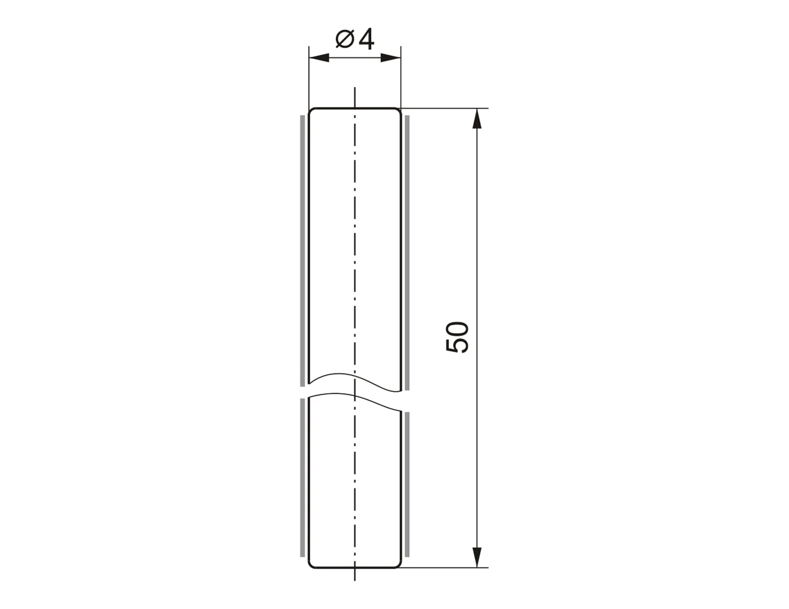
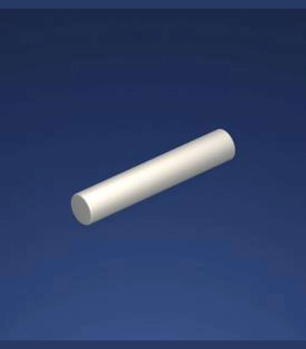
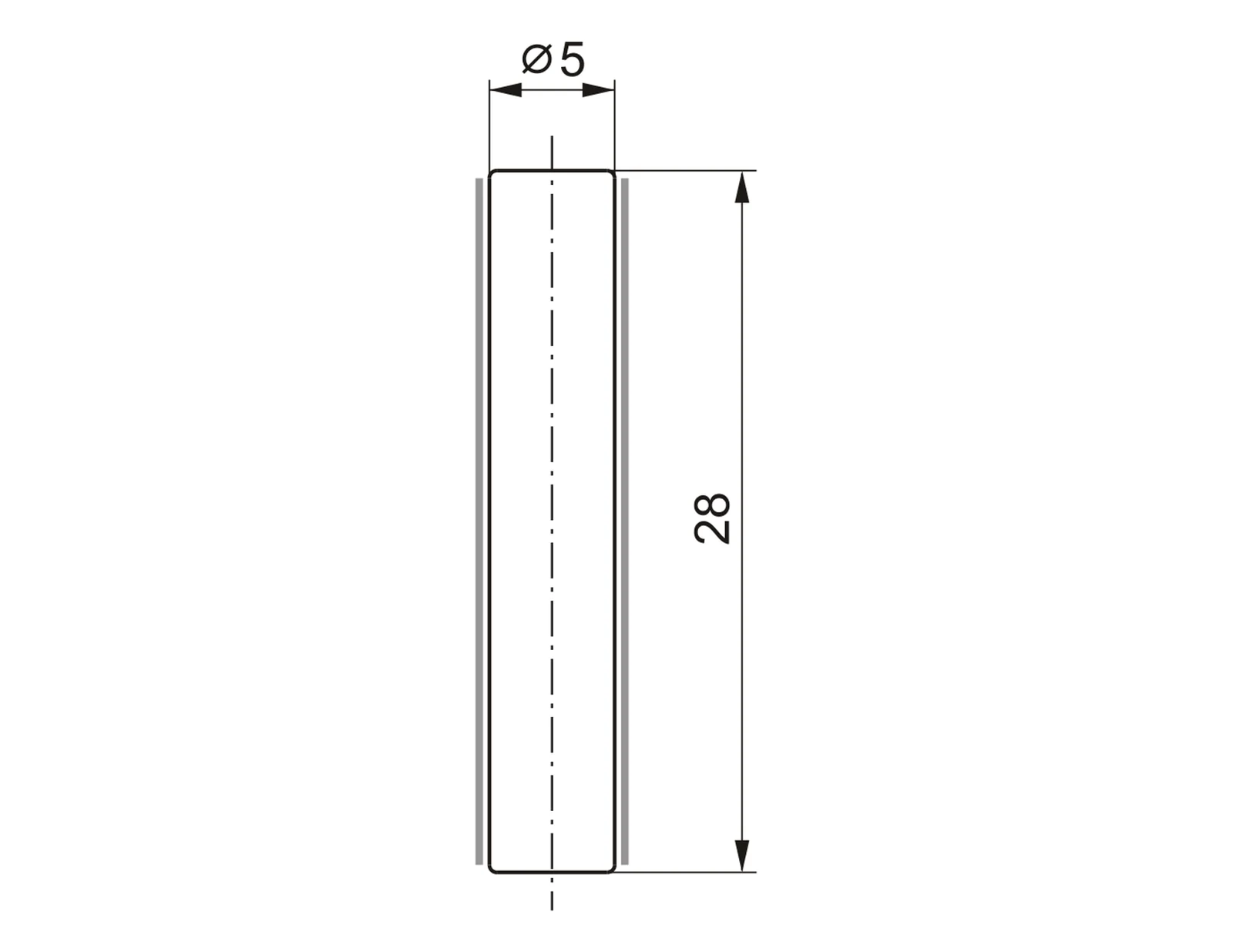
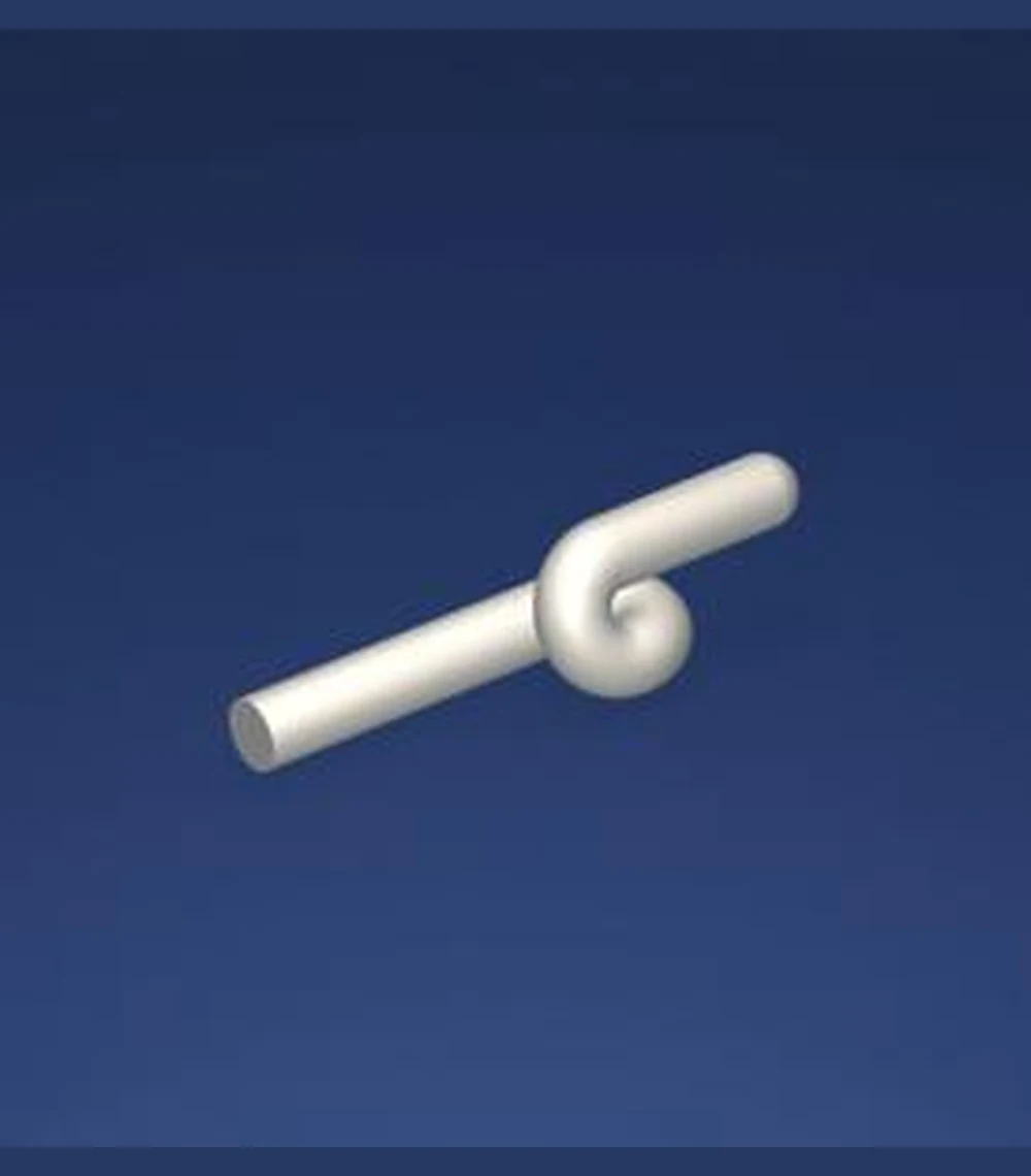
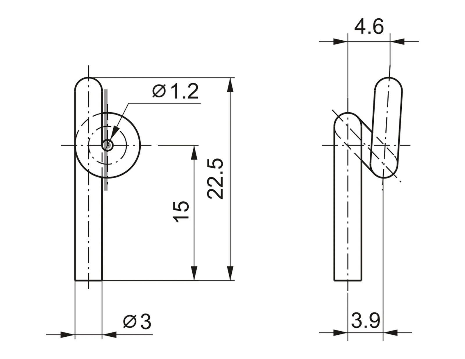
Dimensions in millimetres · Drawings not to scale · Grey line indicates yarn contact surface
Ceramic Yarn Guides
Barmag Ceramic Yarn Guides
Wear resistant and yarn friendly loop, eyelet and profiled guides in 99.7% alumina.
TF997-1247Barmag Ref. 083787/099.7% ALUMINA · Loop Guide · Ø3 × 22.5 |
TF997-1249Barmag Ref. 260370/999.7% ALUMINA · Eyelet Guide · Ø6 × 25 | ||||
TF997-1250Barmag Ref. 252820/399.7% ALUMINA · Eyelet Guide · Ø6 × 25 |
TF997-1280Barmag Ref. C23934499.7% ALUMINA · Profile Guide · 20 × 40 × 2 |
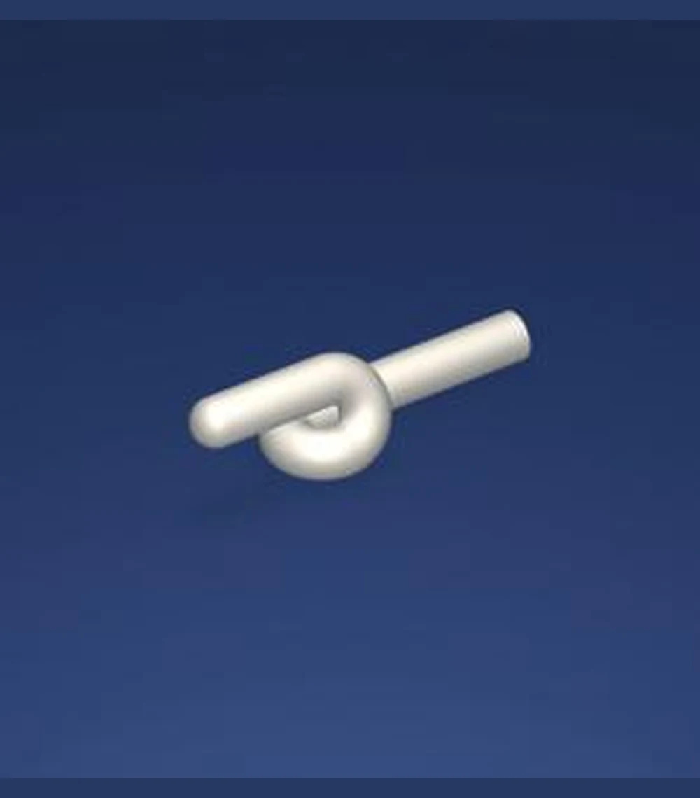
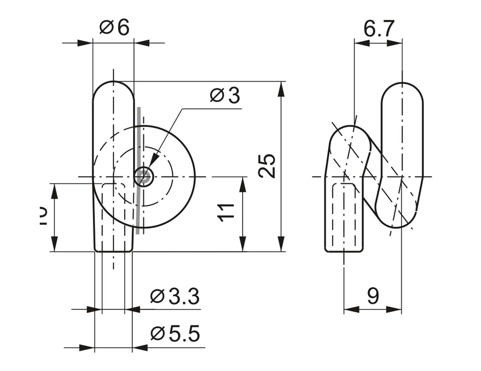
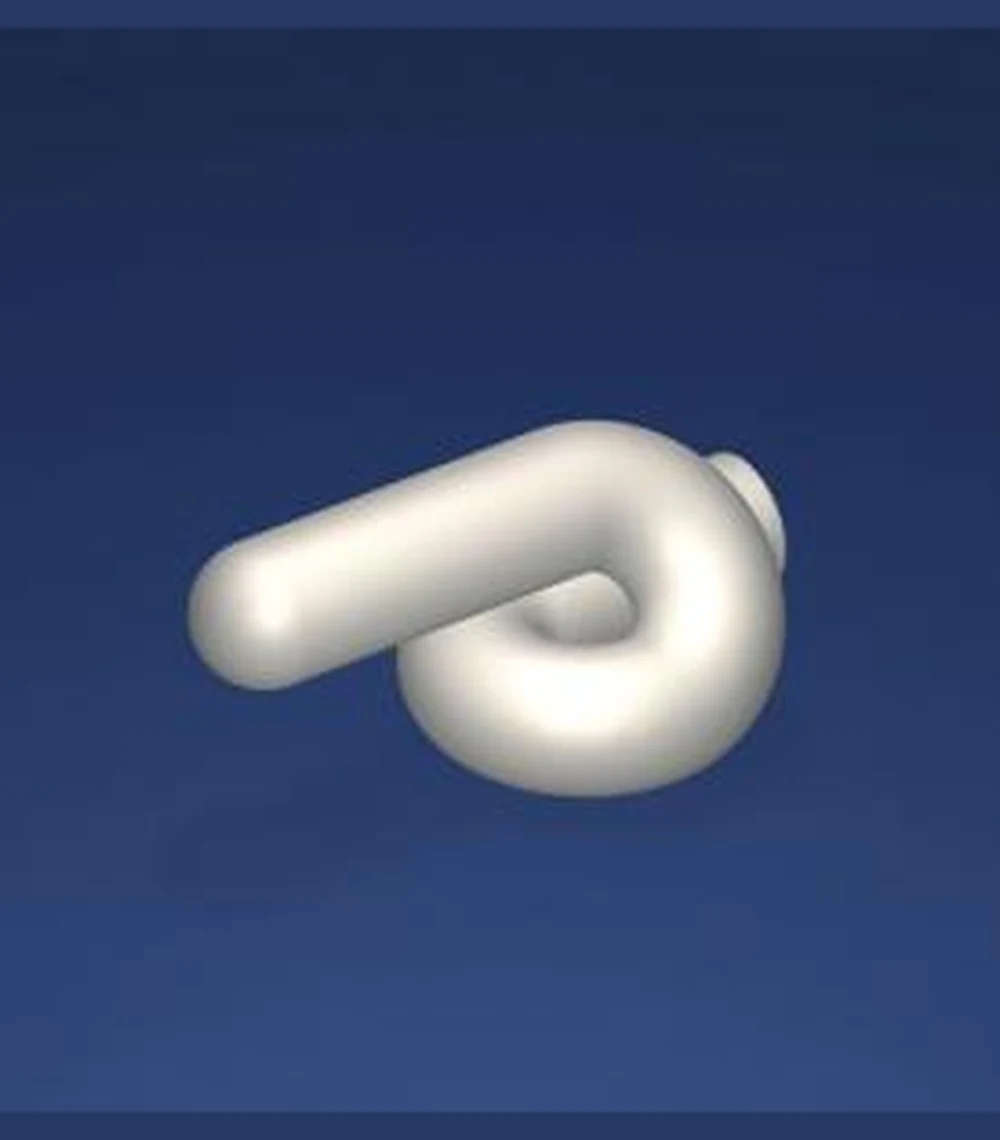
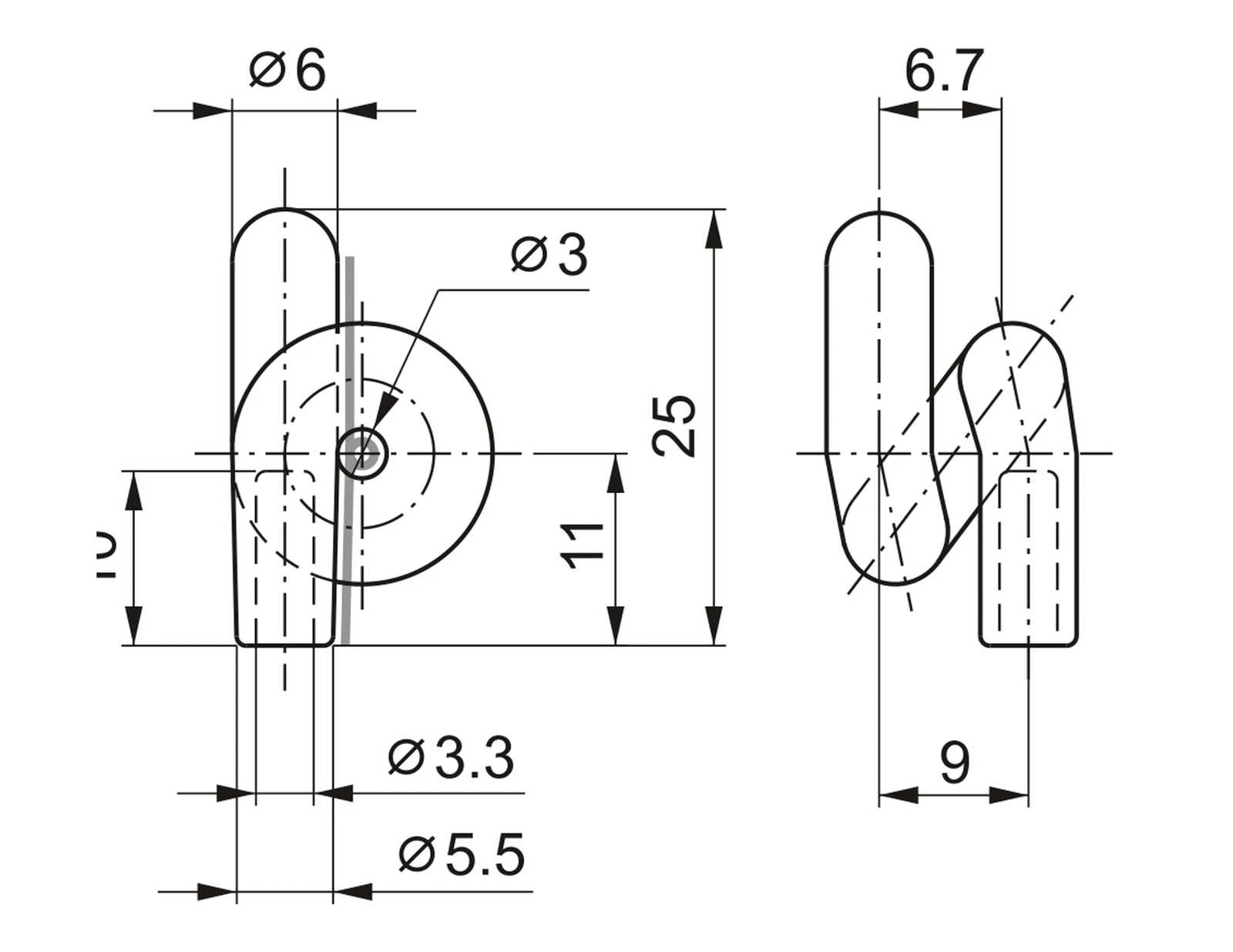
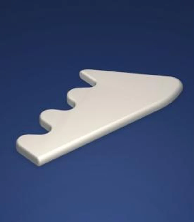
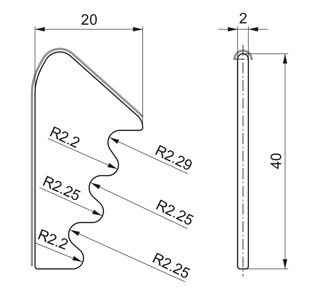
Dimensions in millimetres · Drawings not to scale · Confirm OEM reference and installation position
Ceramic Guide Inserts
Precision Inserts - Series I
Controlled yarn contact profiles in high purity 99.7% alumina.
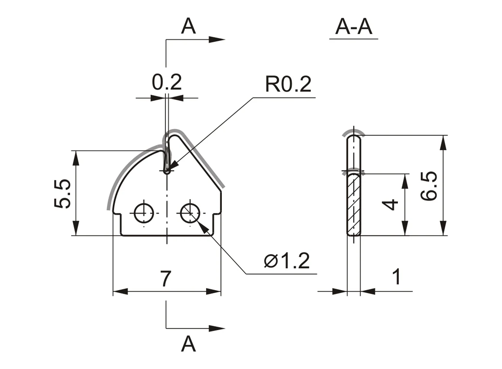
TF997-130699.7% ALUMINA · Precision Ceramic Guide |
TF997-121399.7% ALUMINA · Precision Ceramic Guide | ||||
TF997-131399.7% ALUMINA · Precision Ceramic Guide |
TF997-121599.7% ALUMINA · Precision Ceramic Guide |
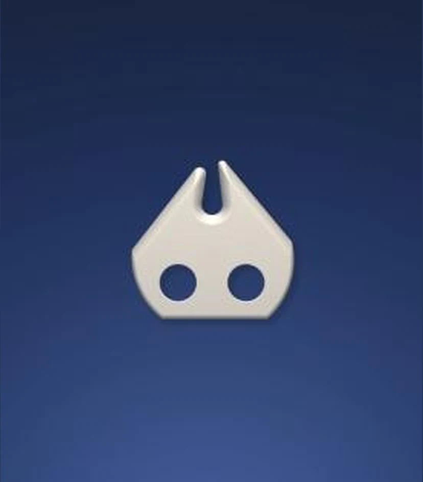
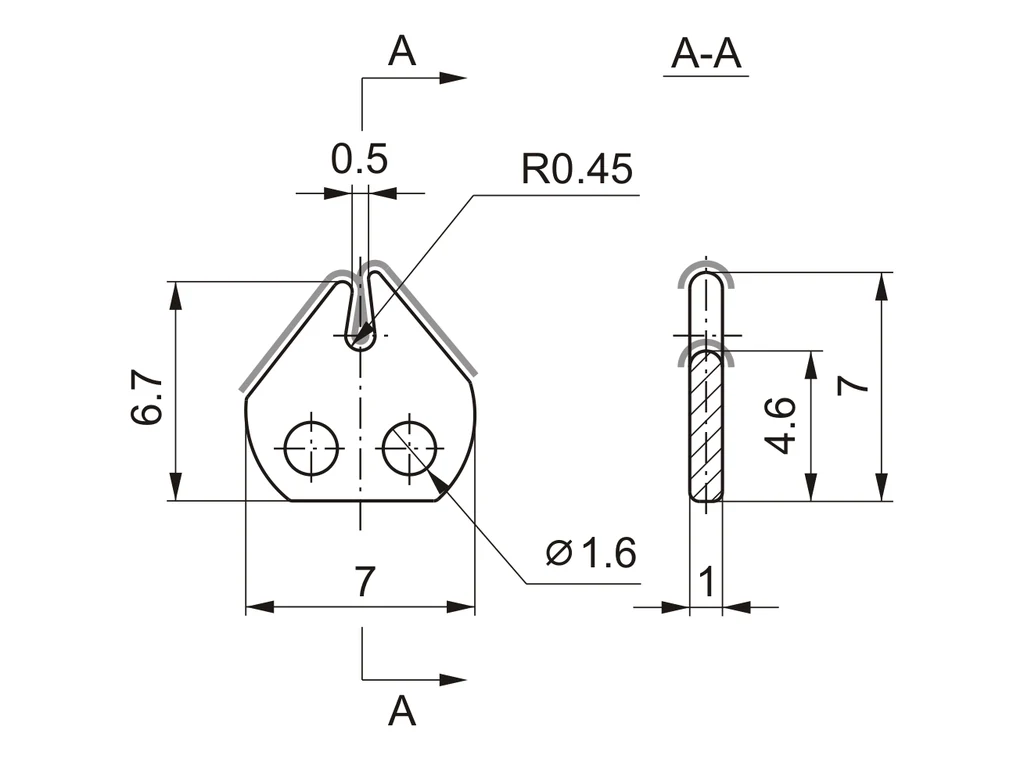
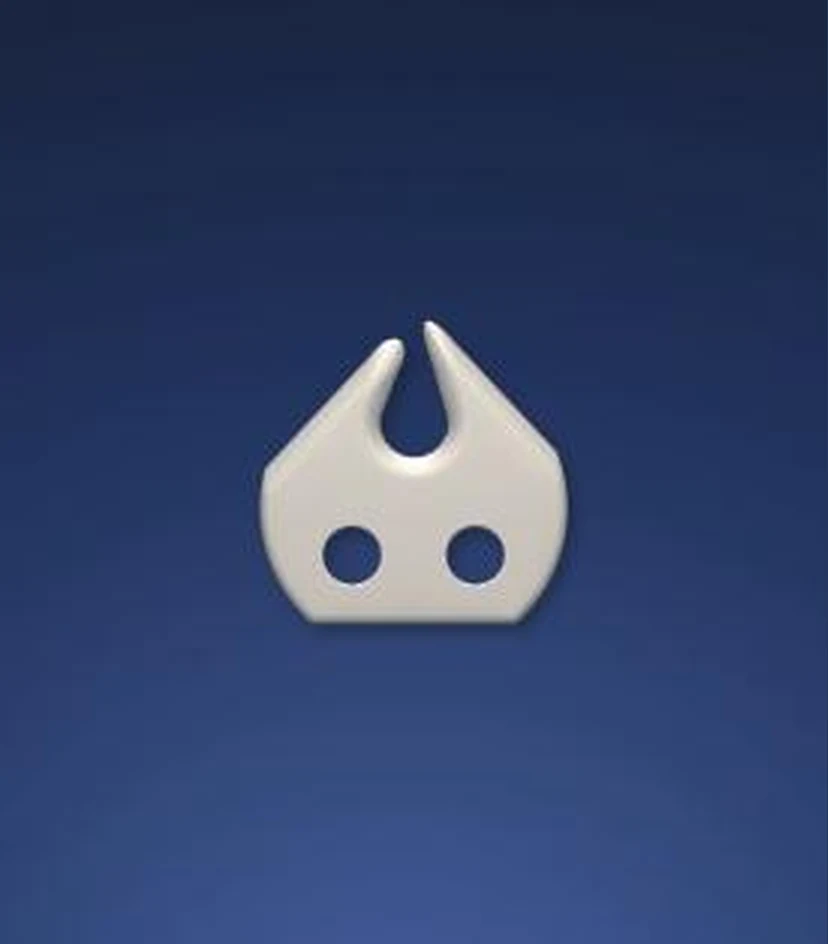
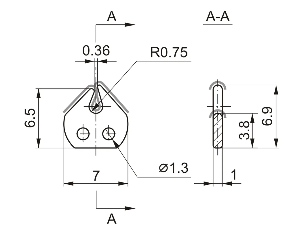
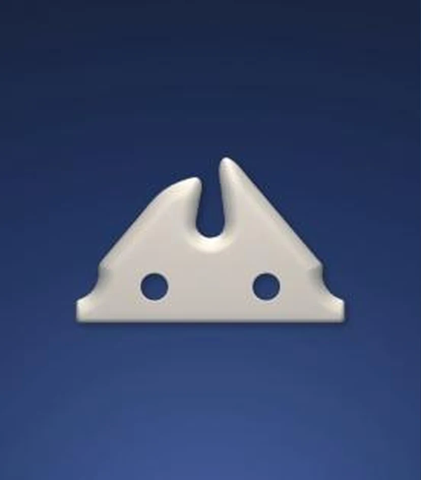
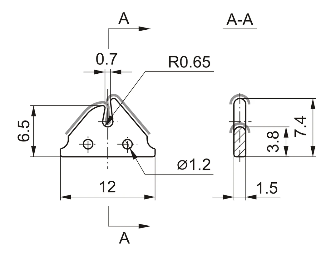
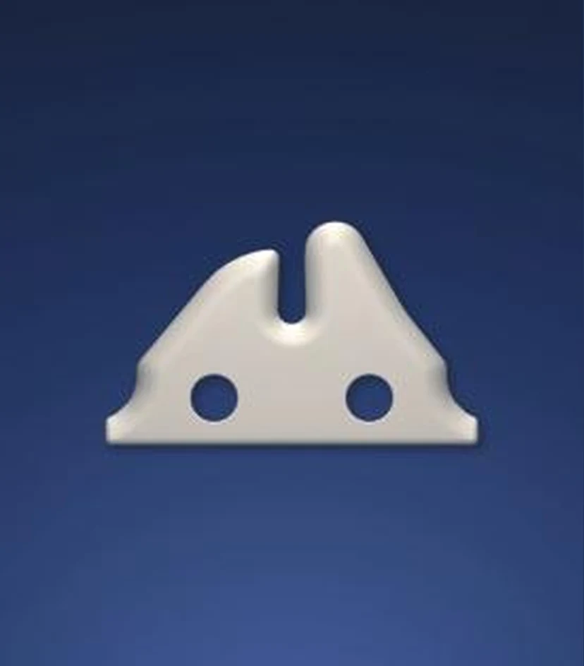
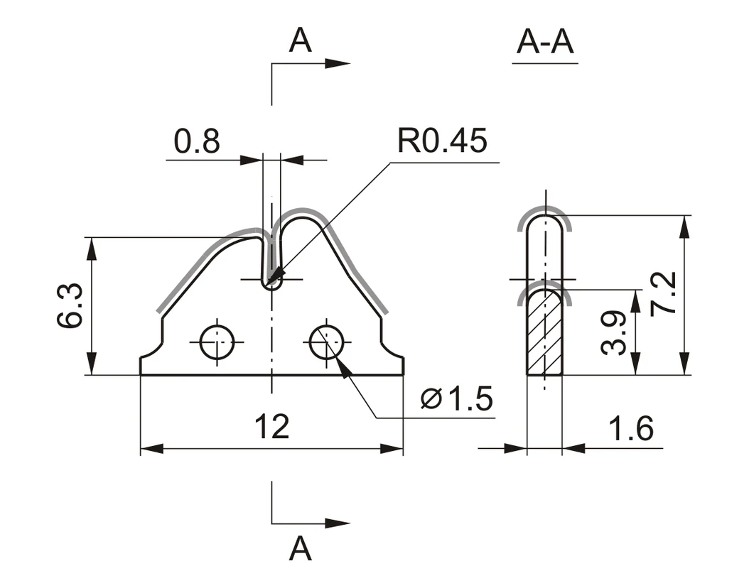
Select by slot width, radius, overall profile, hole pattern and assembly position
Ceramic Guide Inserts
Precision Inserts - Series Ii
Additional guide geometries for application matched yarn contact.
TF997-121699.7% ALUMINA · Precision Ceramic Guide |
TF997-121999.7% ALUMINA · Precision Ceramic Guide | ||||
TF997-121899.7% ALUMINA · Precision Ceramic Guide |
TF997-122099.7% ALUMINA · Precision Ceramic Guide |
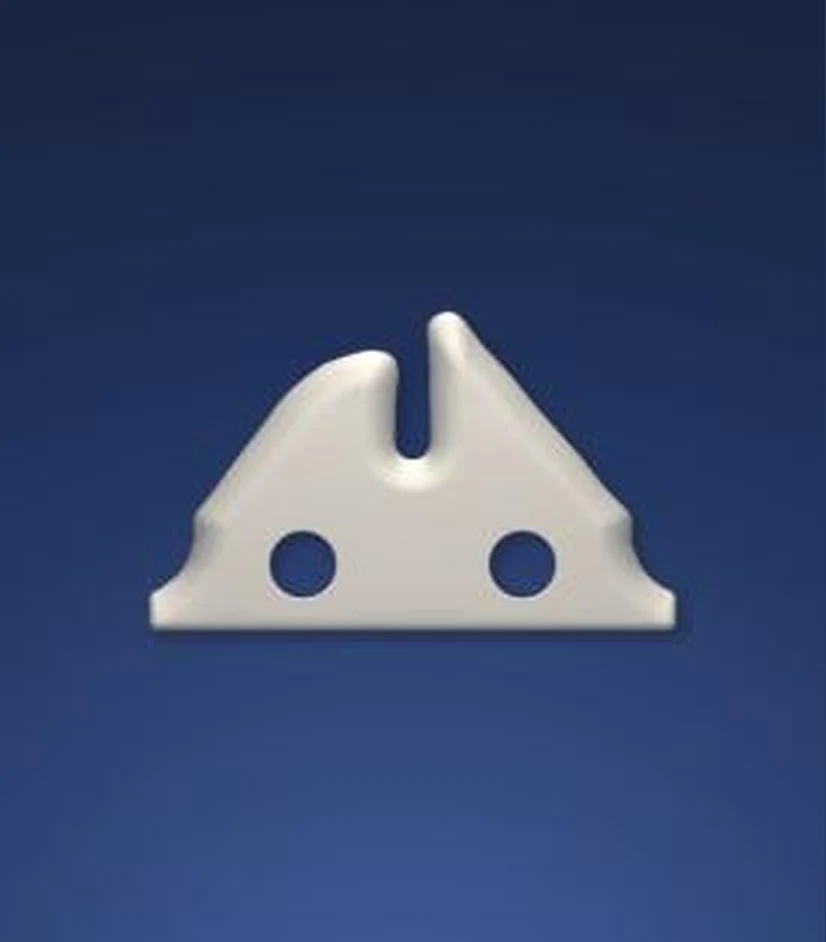
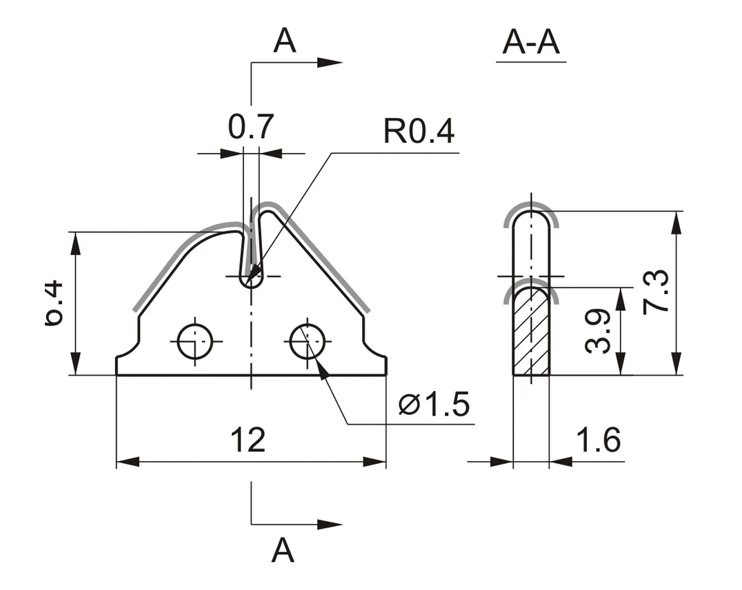
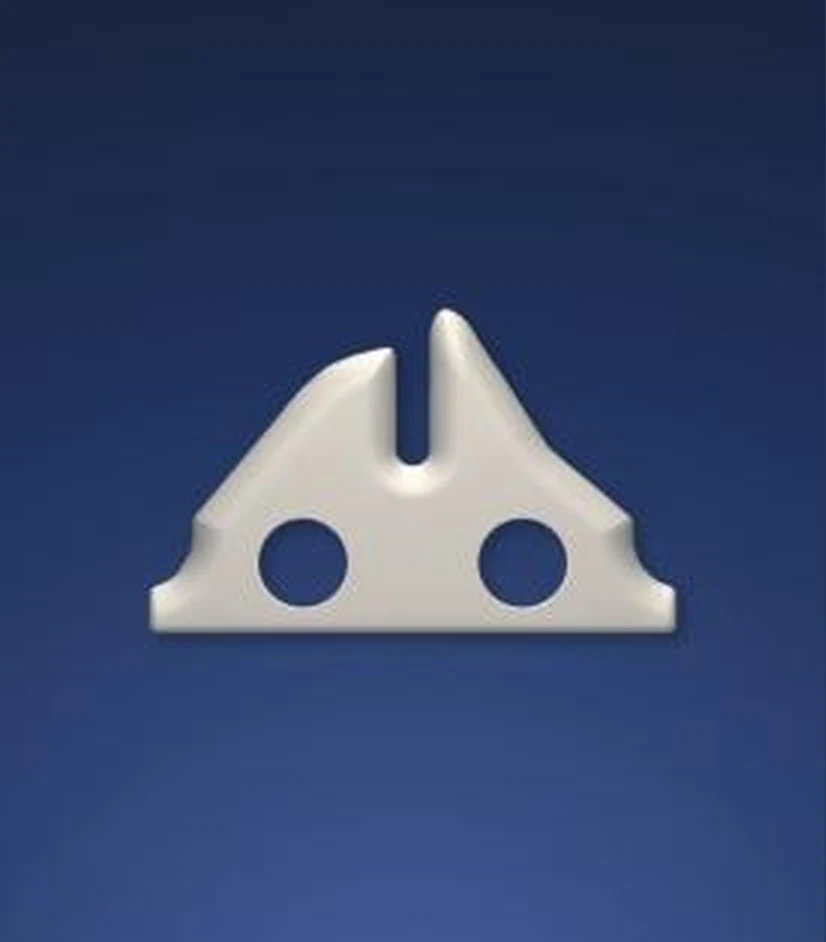
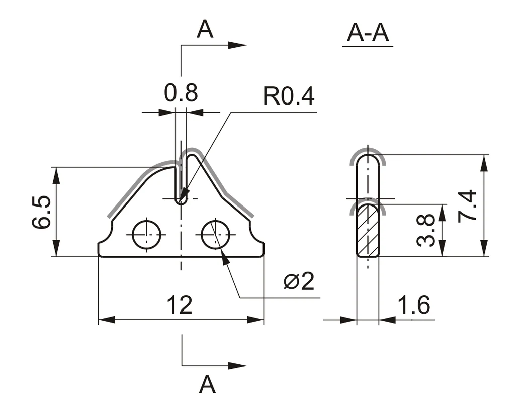
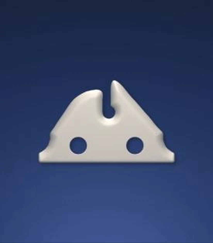
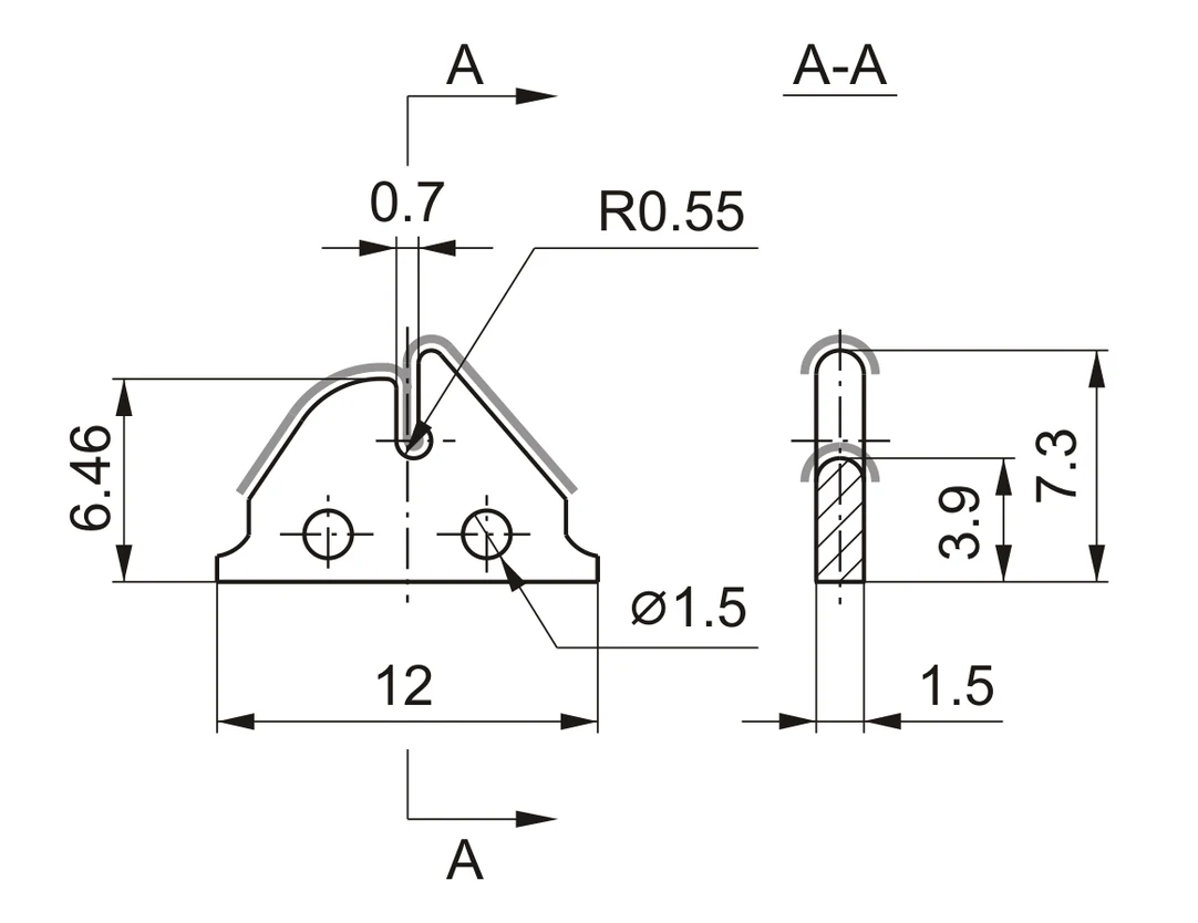
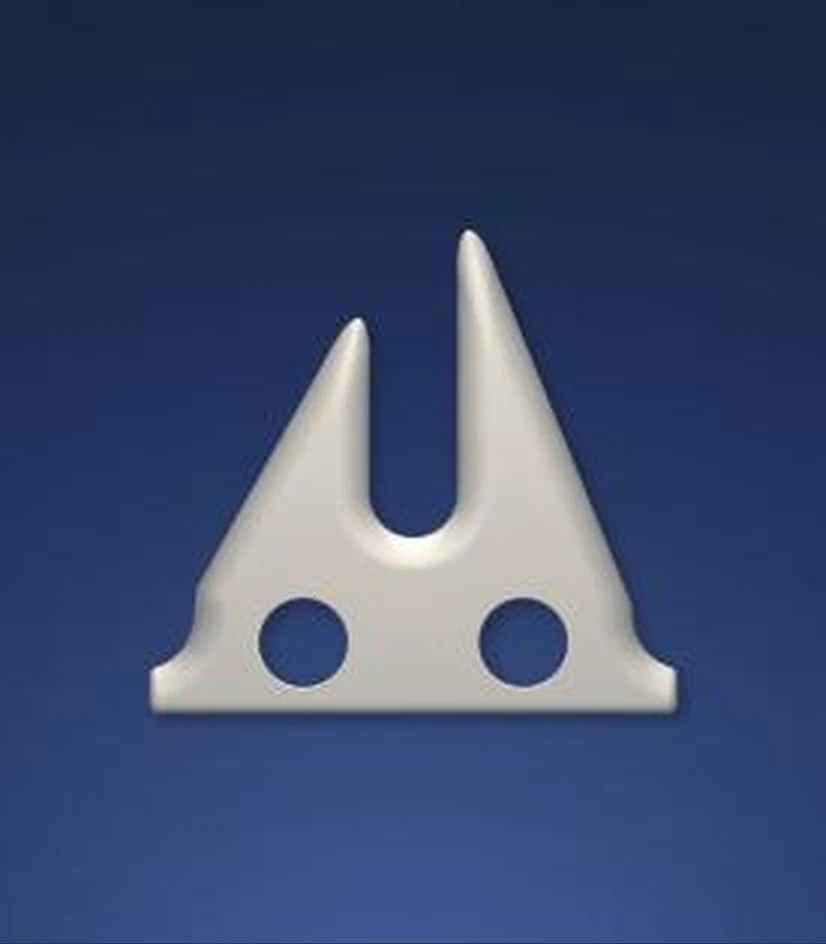
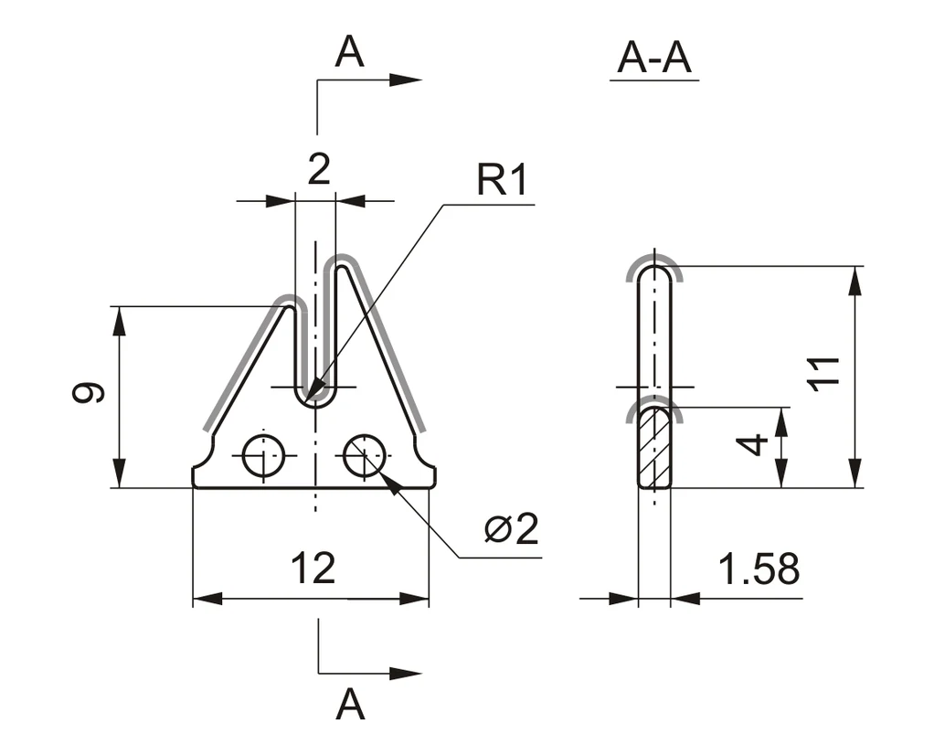
Dimensions in millimetres · Drawings not to scale · Verify yarn contact radius before order
Profiled Ceramic Guides
Profiled Ceramic Winder Guides
Wear resistant and yarn friendly 99.7% alumina profiles with dimensional drawings.
TF997-128099.7% ALUMINA · Profile Guide · 20 × 40 × 2 |
TF997-131599.7% ALUMINA · Profile Guide · 20 × 40 × 2 | ||||
TF997-150799.7% ALUMINA · Precision Ceramic Guide |
TF997-150899.7% ALUMINA · Precision Ceramic Guide |

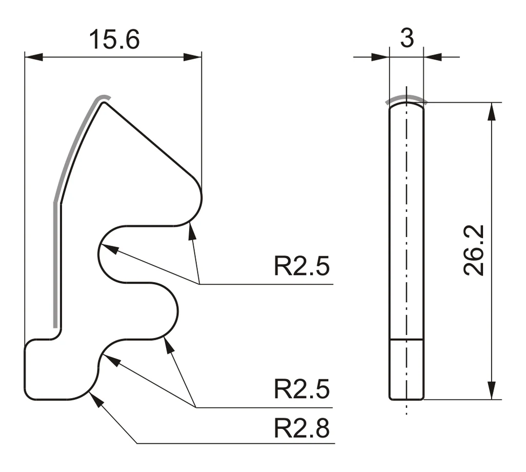

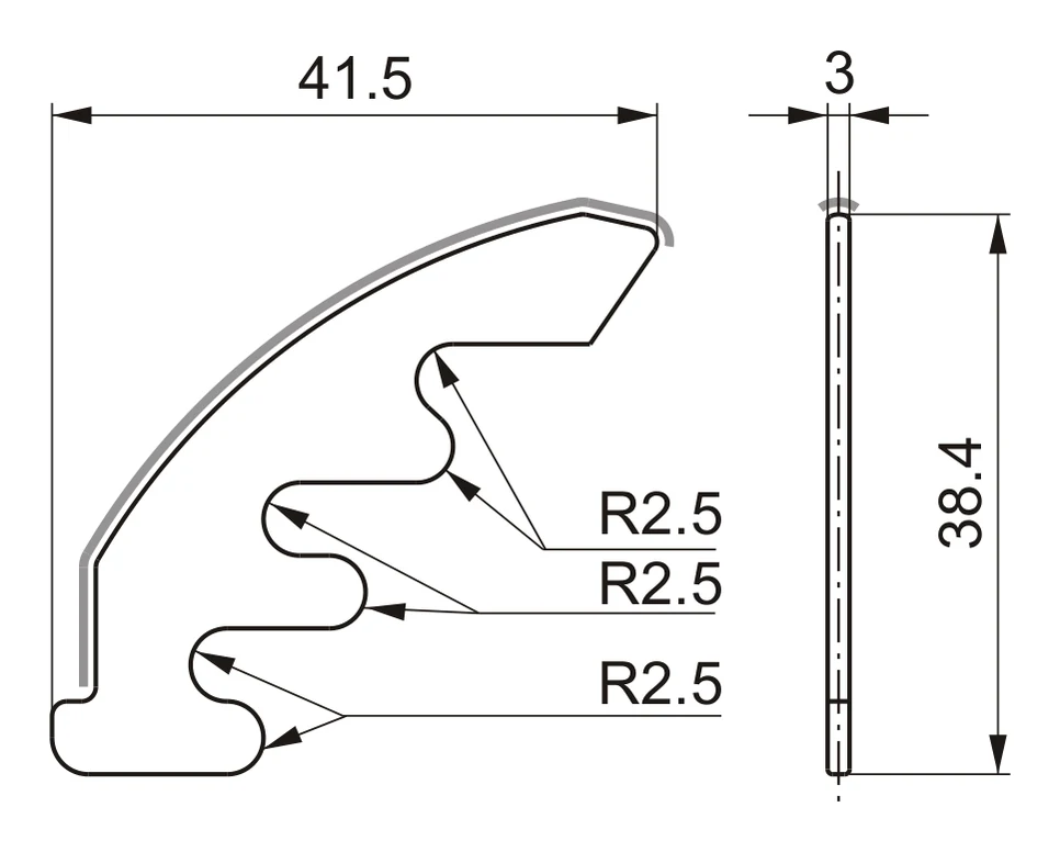
Match the complete profile, thickness, radii and mounting position
Take up Winder Components
Barmag Take up Winder Components
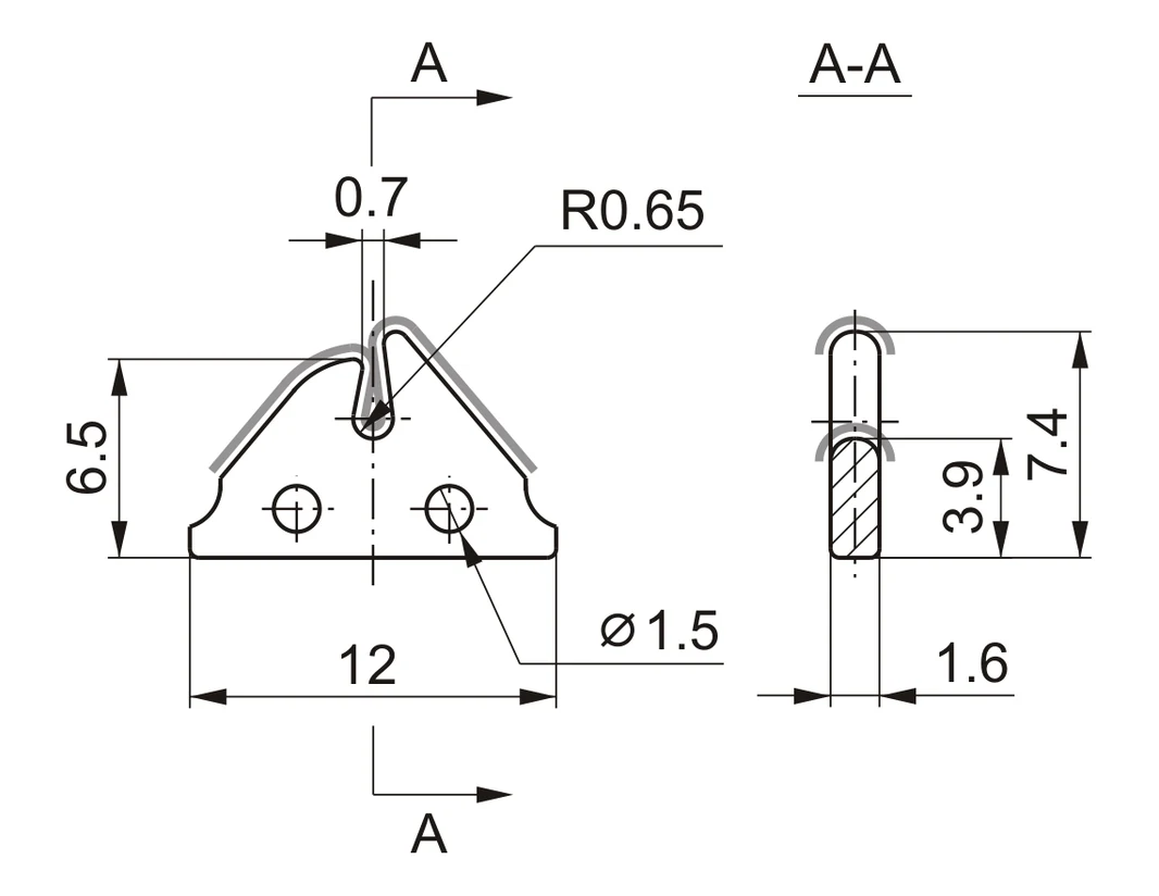
TF-1476 assembly with associated 99.7% alumina guide references.
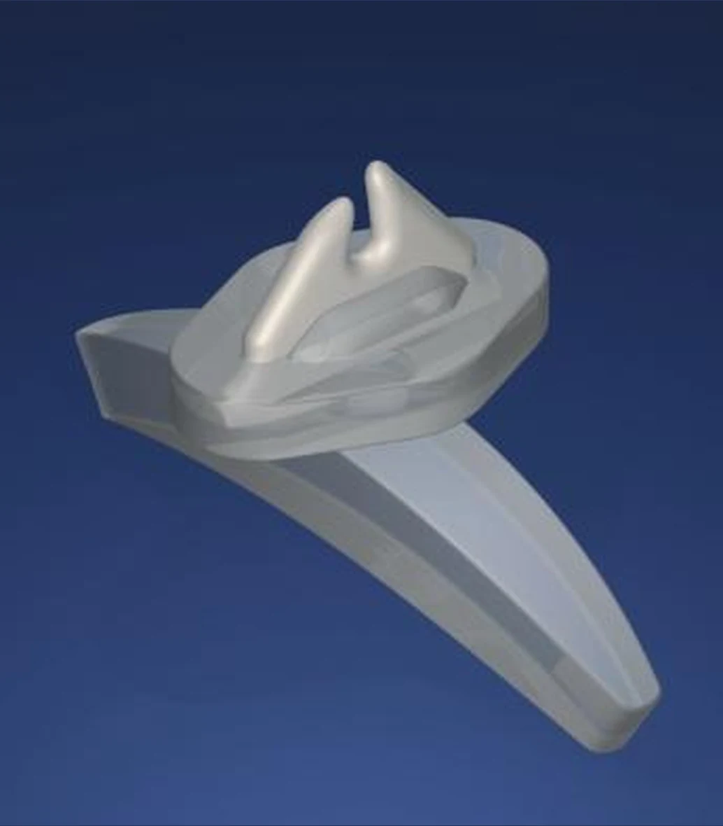 TF-1476Material 99.7% AluminaBarmag Ref. 4674878 (3220866)Take Up Winder Guide · TF997-1213 Plastic Shoe · 1111-T-1008 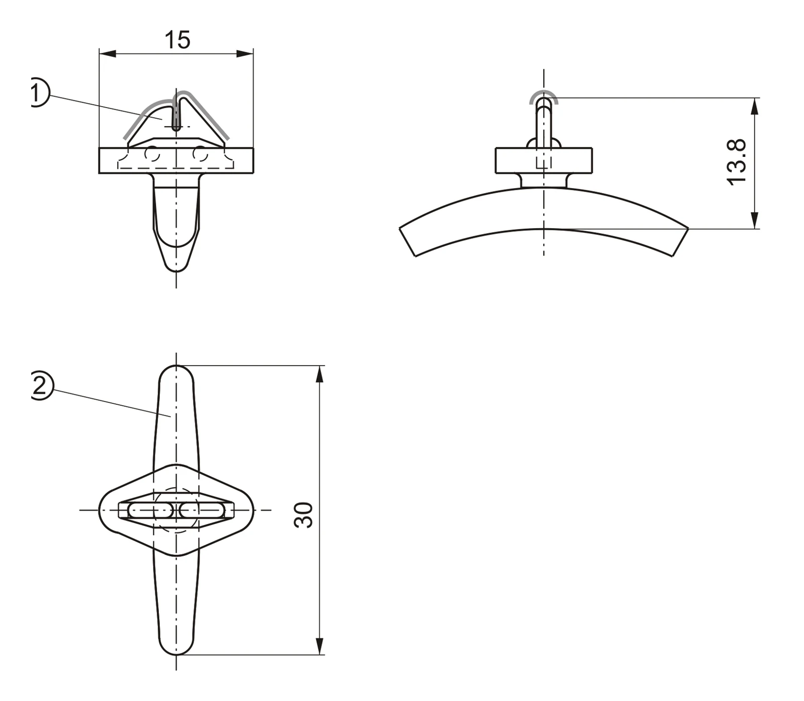 |
TF997-1315Barmag Ref. C23934499.7% ALUMINA · Profile Guide · 20 × 40 × 2 | ||
TF-1476Material 99.7% AluminaBarmag Ref. 4674878 (3220866)Take Up Winder Guide · TF997-1213 Plastic Shoe · 1111-T-1008 |
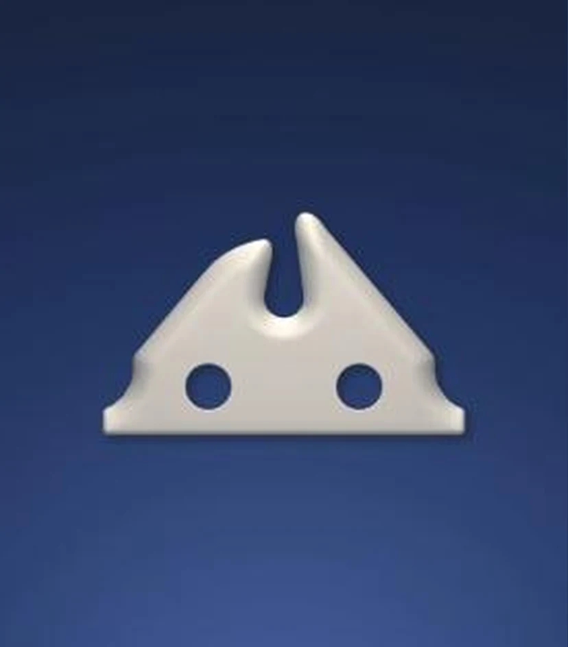
TF997-1213Matching Take up Winder Guide99.7% ALUMINA · Precision Ceramic Insert |
Take up Winder Assemblies
Take up Winder Guide Assemblies - Series I
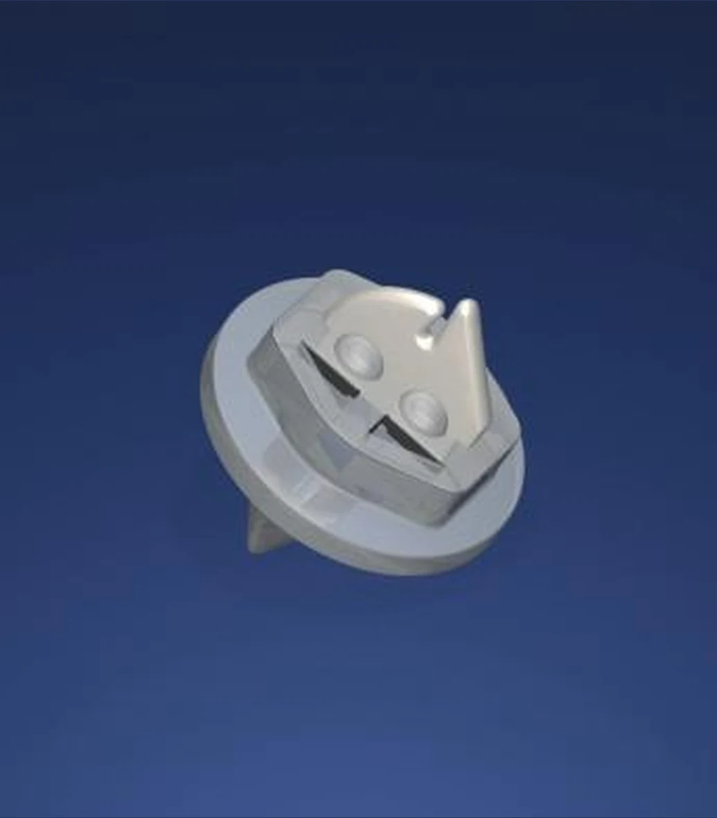
High purity and yarn friendly ceramic guide assemblies with matching winder and nylon shoe references.
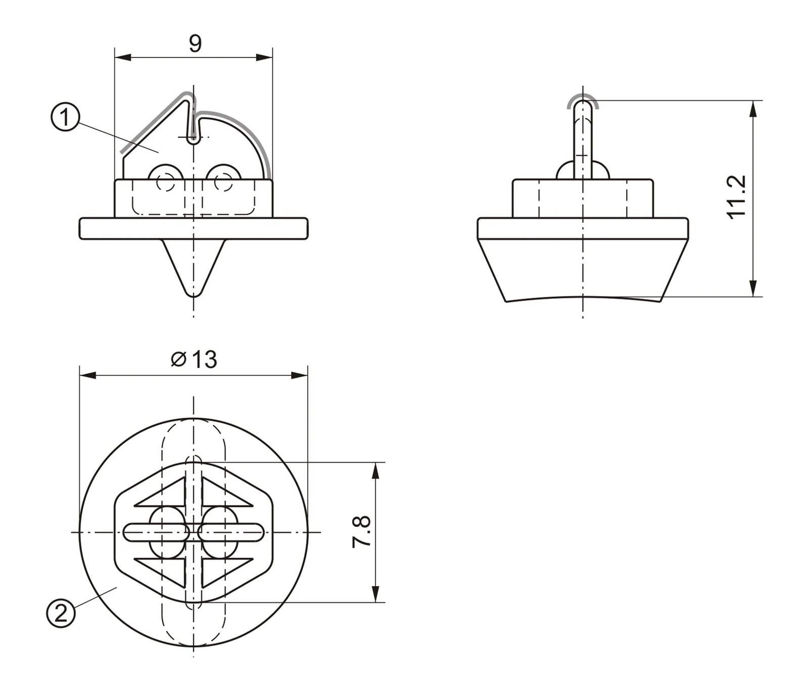
TF-1478MATERIAL Al₂O₃ · 99.7% Take up WinderTF997-1307Plastic Shoe · Nylon1111-T-1010SIZE (mm) W 9 · H 11.2 · Ø13 · Guide 7.8 |
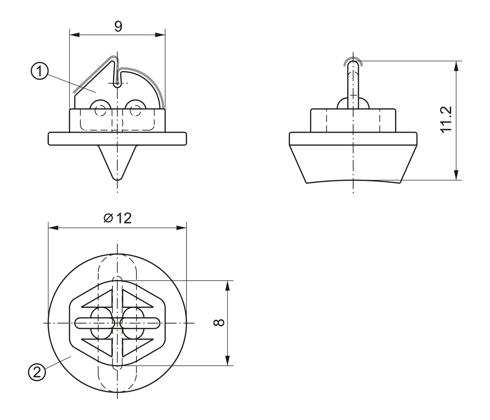
TF-1605MATERIAL Al₂O₃ · 99.7% Take up WinderTF997-1307Plastic Shoe · Nylon1111-T-1058SIZE (mm) W 9 · H 11.2 · Ø12 · Guide 8 |
Dimensions in millimetres · Drawings not to scale · Match shoe and guide as a complete configuration
Take up Winder Assemblies
Take up Winder Guide Assemblies - Series Ii
Alternative assembly geometries for position specific replacement.
TF-1557MATERIAL Al₂O₃ · 99.7% Take up WinderTF997-1209Plastic Shoe · Nylon1111-T-1045SIZE (mm) W 9 · H 11.7 · Ø13 · Guide 8 |
TF-1477MATERIAL Al₂O₃ · 99.7% Take up WinderTF997-1307Plastic Shoe · Nylon1111-T-1009SIZE (mm) W 7.9 · H 11.3 · Base 12 × 13 |
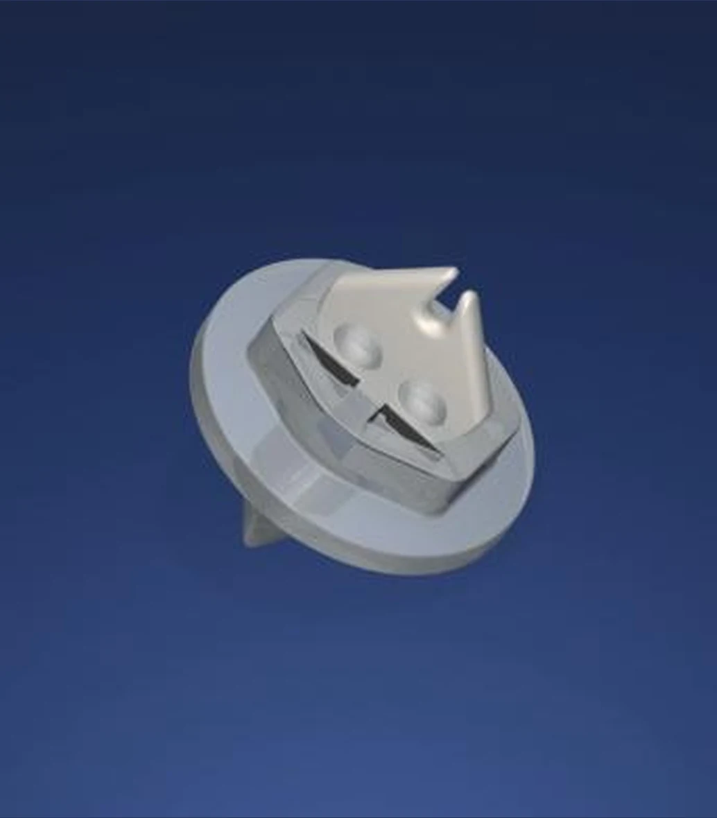
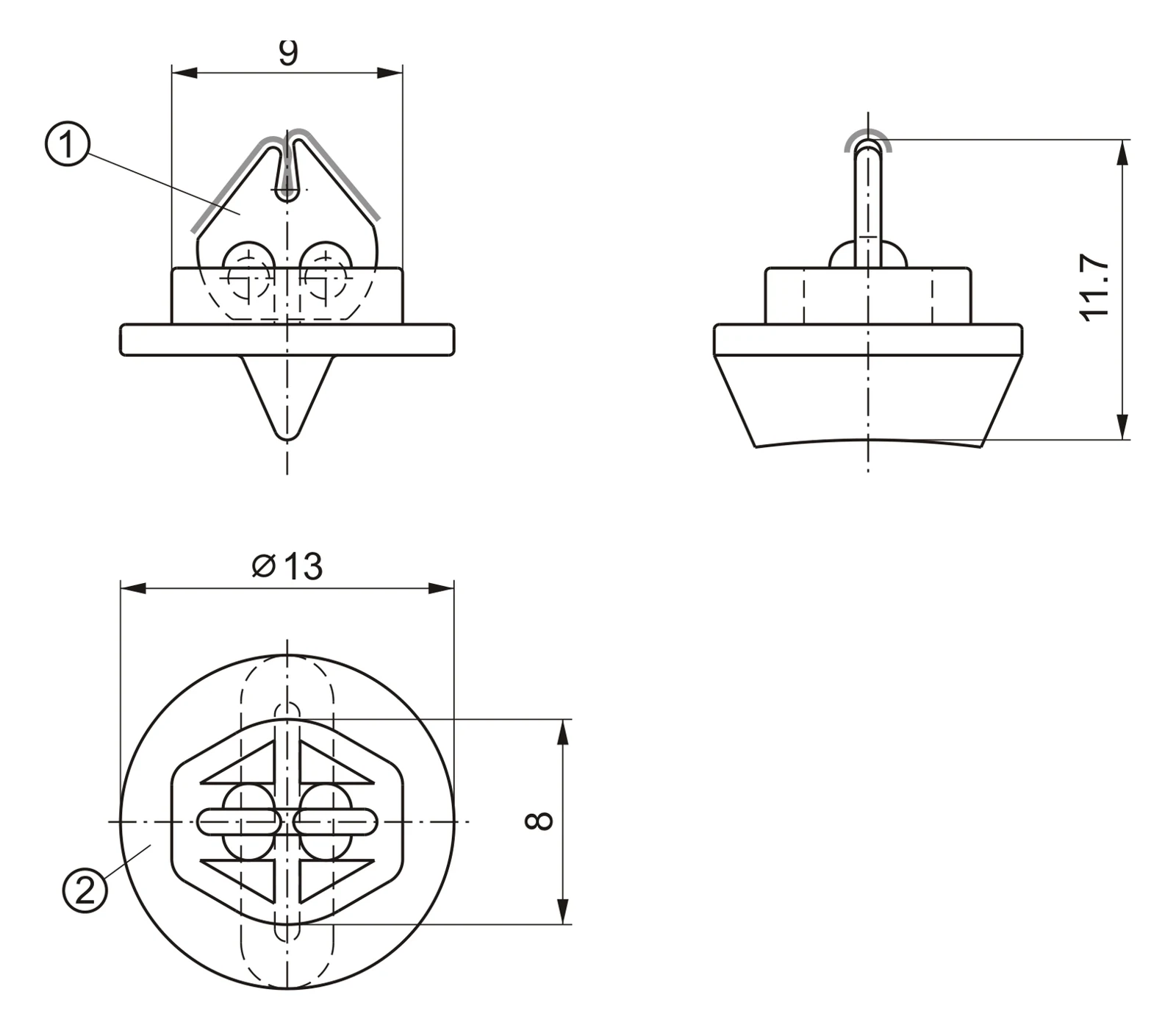
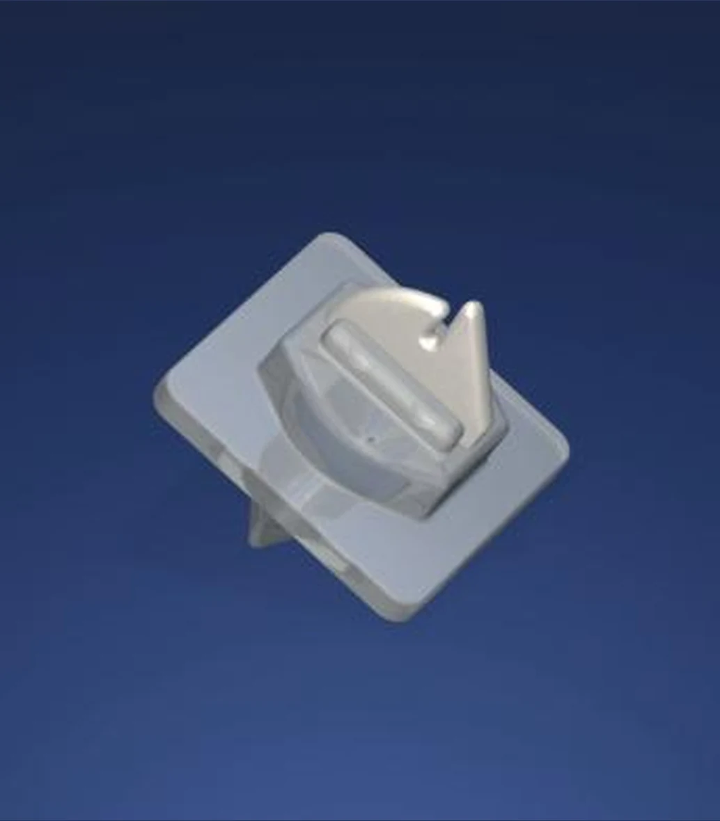
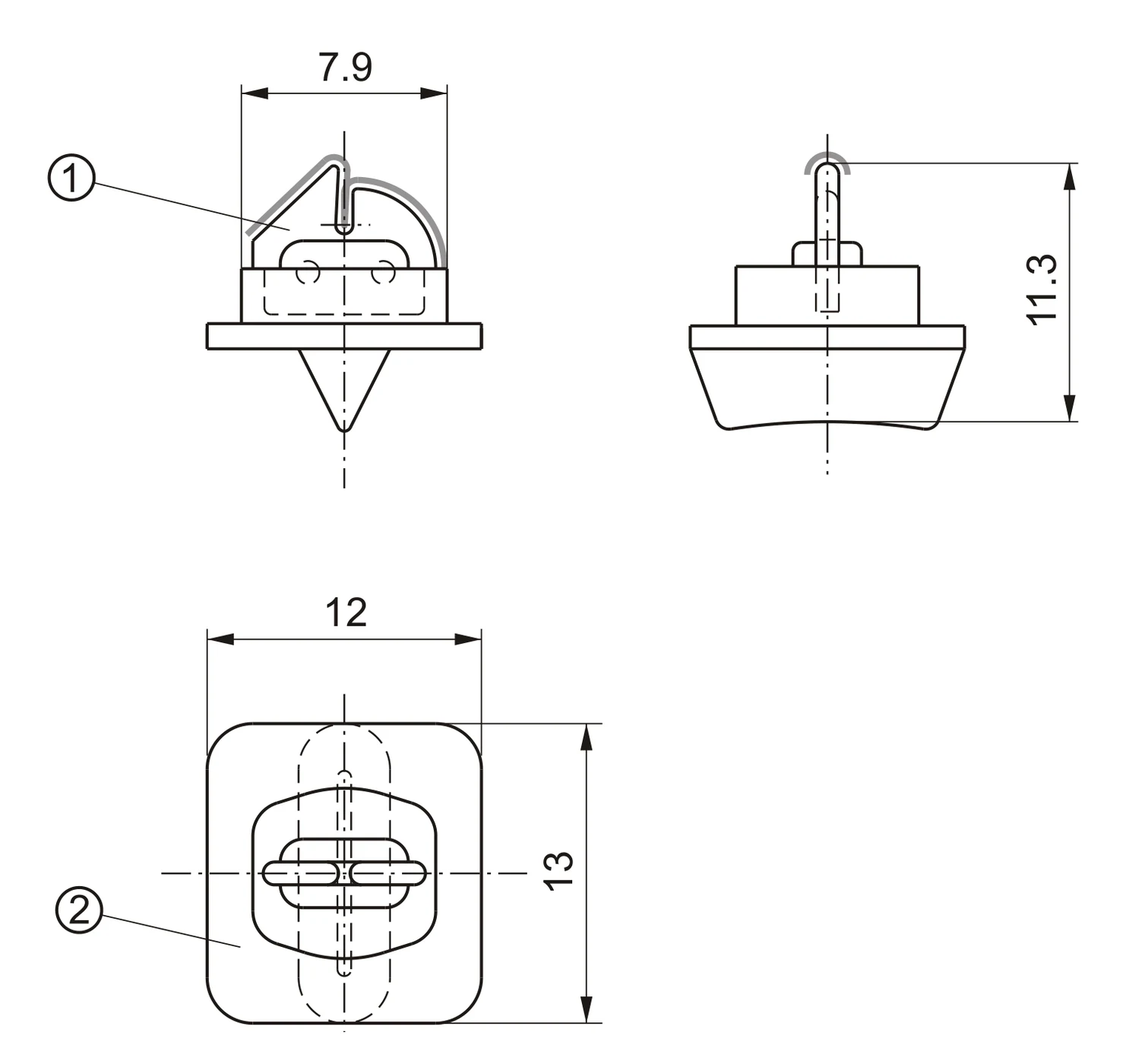
Confirm base geometry, mounting pattern, ceramic profile and guide orientation
Assembly Matching
Assembly & Matching Ceramic Inserts
Selection reference for winder assembly TF-1476 and associated guide geometries.
TF-147699.7% Alumina · Take up WinderTF997-1213 · Plastic Shoe 1111-T-1008 |
|
Traverse Components
Bi - Rotor Traverse
Controlled yarn transfer through application matched rotor geometry.
01 Counter Rotating Wing Action Opposed rotor wings transfer the yarn at each reversal. | 02 Wear Critical Working Edges Guide edge condition supports consistent yarn transfer. |
|---|---|
03 Application Matched Selection Confirm model, position, direction and mounting pattern. | 04 Identification Support Use clear photographs, existing reference and machine position. |
Representative Models
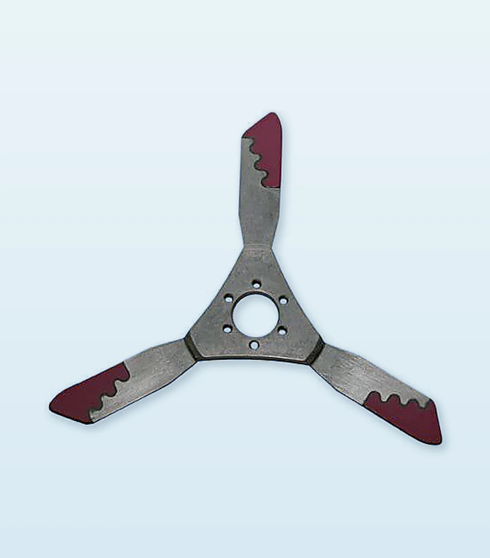 TF-1011 | 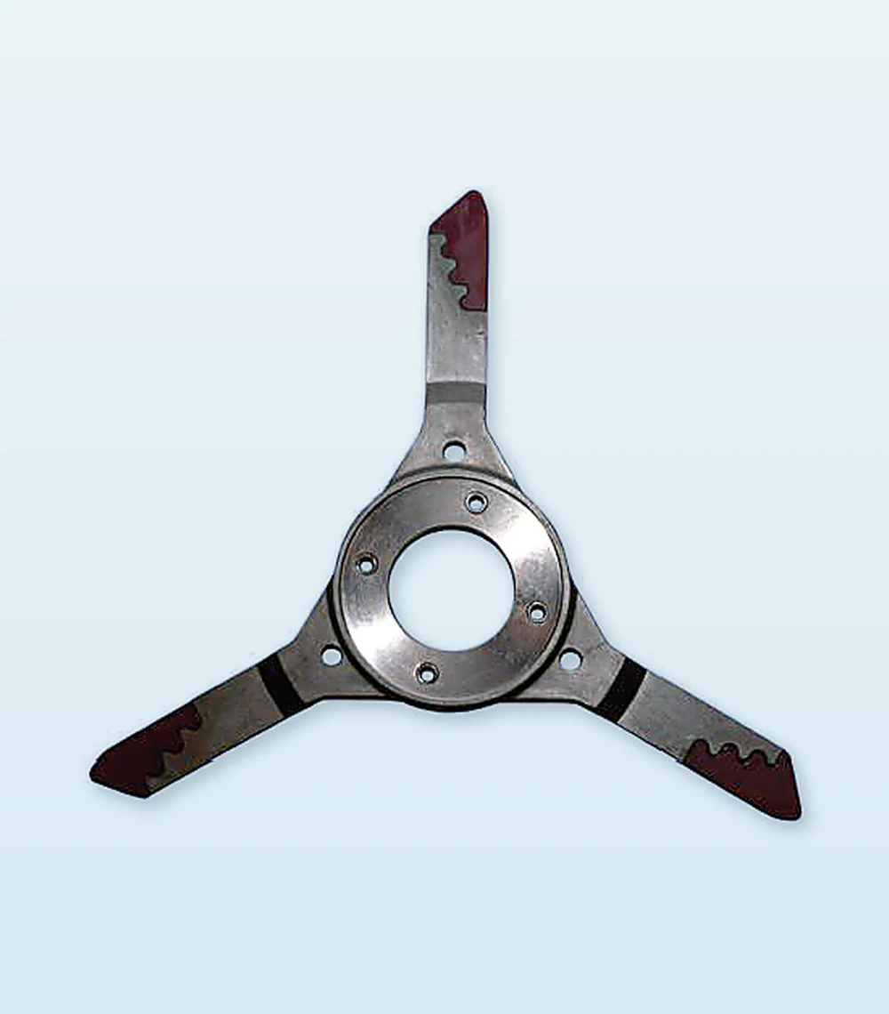 TF-1015 | 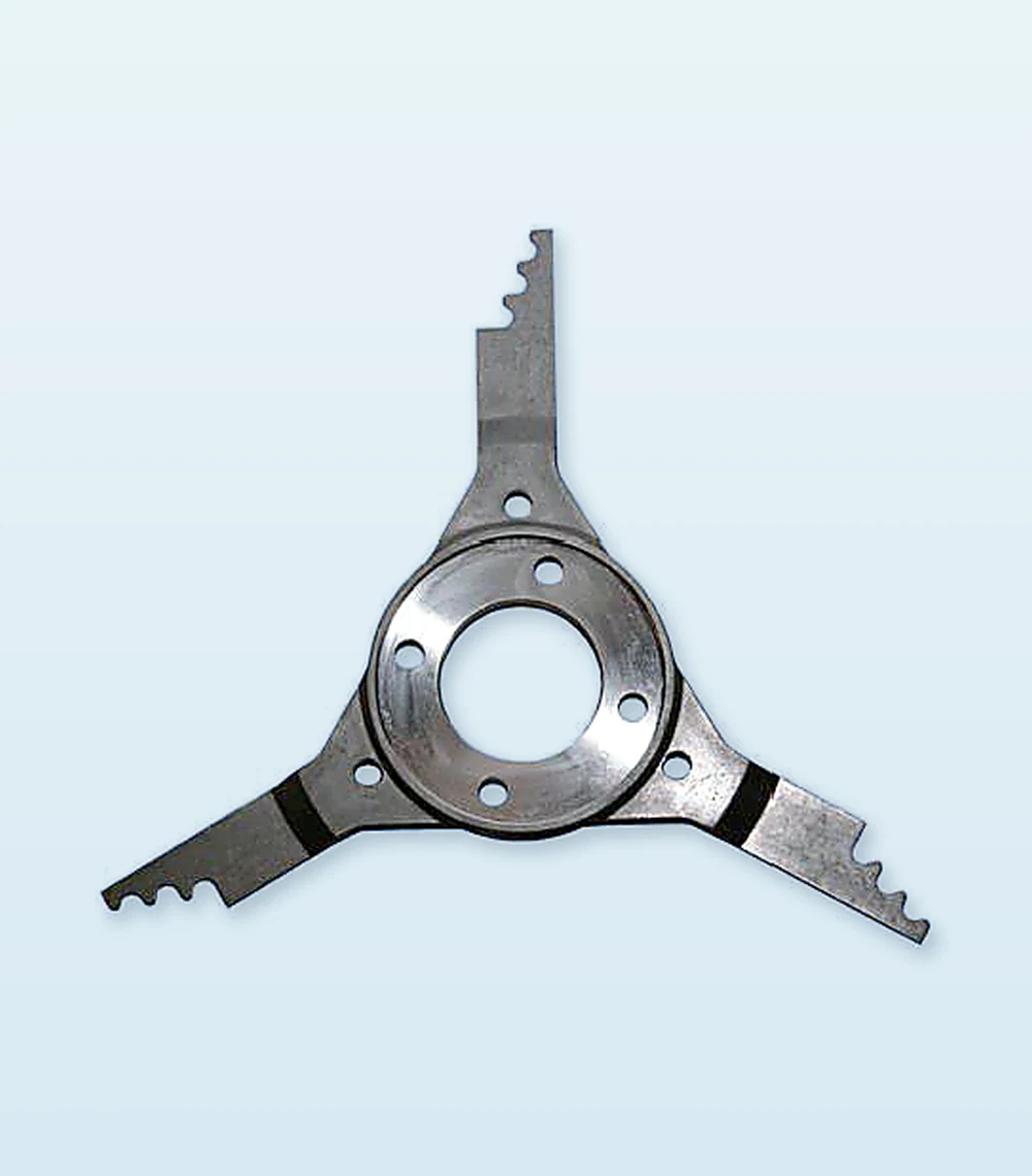 TF-1021 | TF-1024 |
Rotor shape, mounting format and working edge configuration vary by machine position
Bi - Rotor Range
Bi - Rotors - TF1011 to TF1014
Replacement traverse wing assemblies for model and position specific matching.
TF1011Bi Rotor Wing AssemblyMatch rotor position, direction and mounting geometry. | 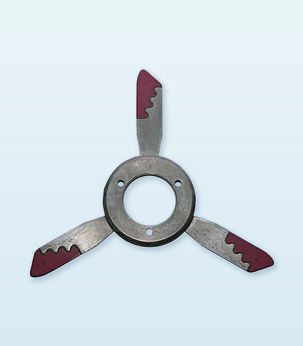 TF1012Bi Rotor Wing AssemblyMatch rotor position, direction and mounting geometry. |
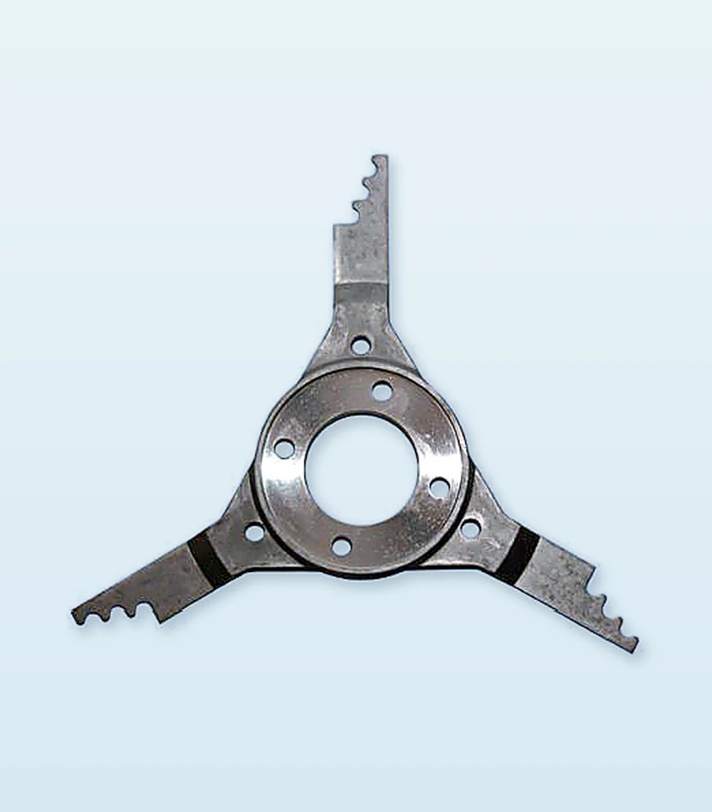 TF1013Bi Rotor Wing AssemblyMatch rotor position, direction and mounting geometry. | 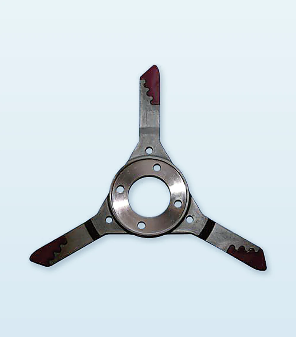 TF1014Bi Rotor Wing AssemblyMatch rotor position, direction and mounting geometry. |
Photographs shown for product identification · Confirm direction, mounting geometry and rotor position
Bi - Rotor Range
Bi - Rotors - TF1015 to TF1018
Replacement traverse wing assemblies matched to the machine model and position.
TF1015Bi Rotor Wing AssemblyMatch rotor position, direction and mounting geometry. | 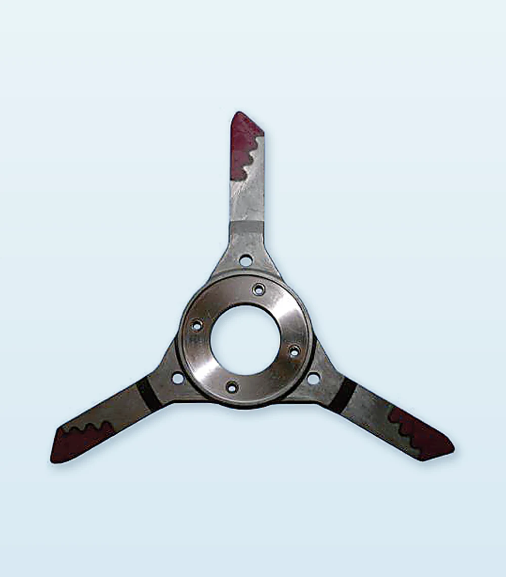 TF1016Bi Rotor Wing AssemblyMatch rotor position, direction and mounting geometry. |
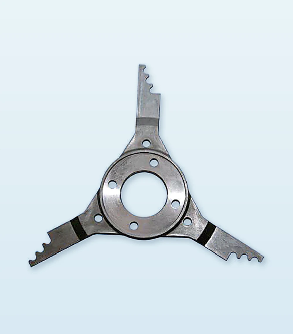 TF1017Bi Rotor Wing AssemblyMatch rotor position, direction and mounting geometry. | 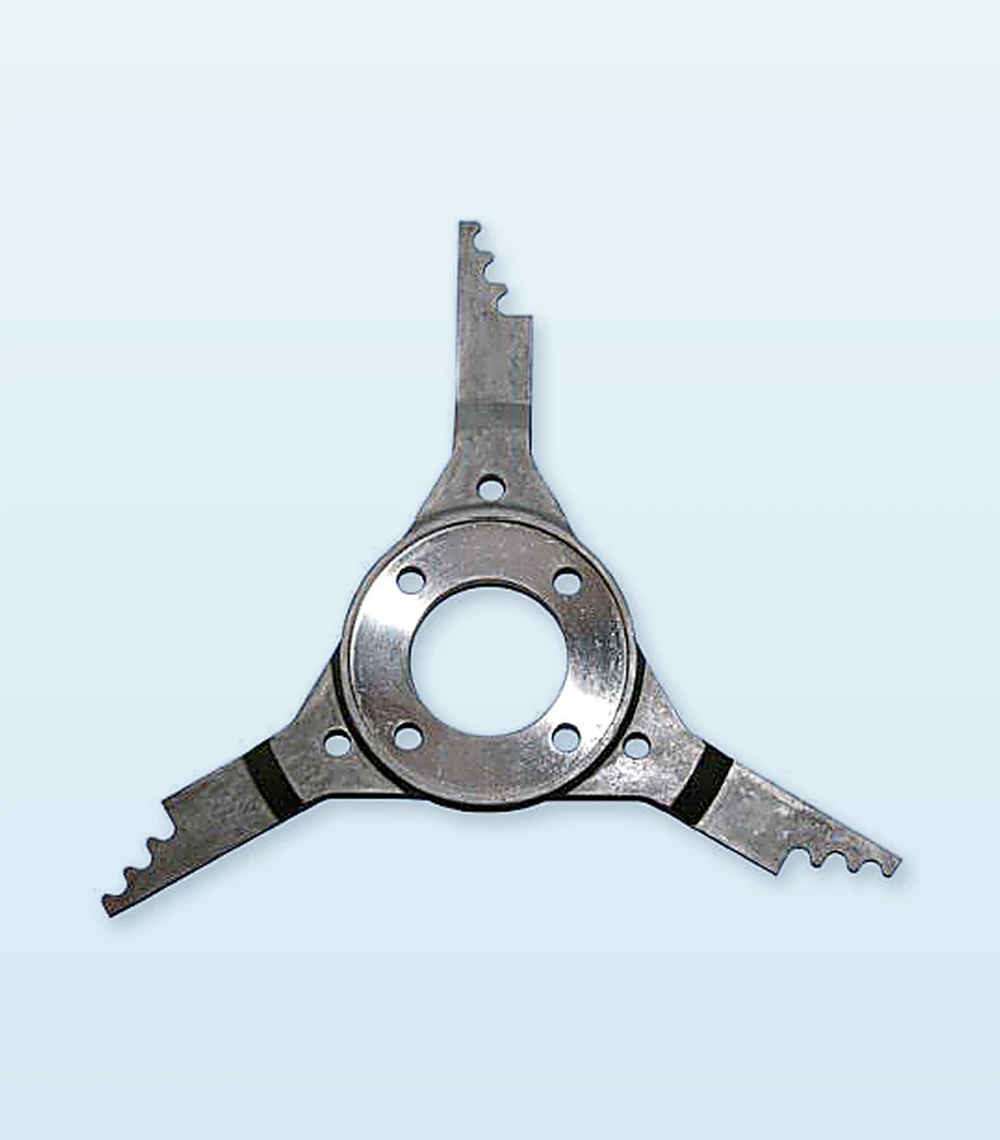 TF1018Bi Rotor Wing AssemblyMatch rotor position, direction and mounting geometry. |
Photographs shown for product identification · Confirm direction, mounting geometry and rotor position
Bi - Rotor Range
Bi - Rotors - TF1021 to TF1024
Replacement traverse wing assemblies for model and position specific matching.
TF1021Bi Rotor Wing AssemblyMatch rotor position, direction and mounting geometry. | 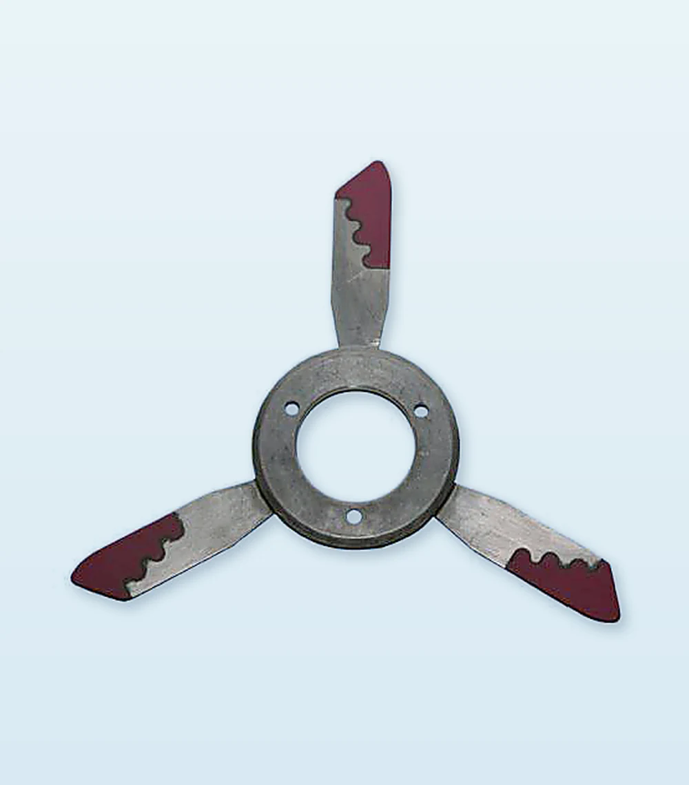 TF1022Bi Rotor Wing AssemblyMatch rotor position, direction and mounting geometry. |
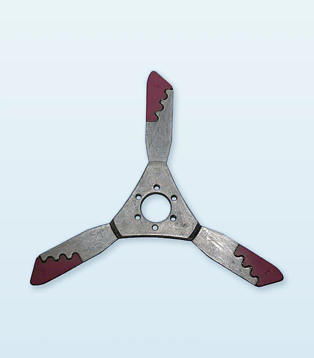 TF1023Bi Rotor Wing AssemblyMatch rotor position, direction and mounting geometry. | TF1024Bi Rotor Wing AssemblyMatch rotor position, direction and mounting geometry. |
Photographs shown for product identification · Confirm direction, mounting geometry and rotor position
Application Support
From Identification to Supply
A clear verification process reduces replacement risk and supports faster quotation.
1IdentifyMachine manufacturer, model, take up position and existing part number. | 2VerifyCompare overall geometry, mounting holes, slot, radius, thickness and yarn contact surface. | 3SpecifyConfirm quantity, operating yarn, speed and recurring wear or quality concern. |
|---|
Send with Your Enquiry
OEM and machine model
Existing part or assembly reference
Clear photographs, dimensional drawing or physical sample
Yarn type, linear density and operating speed
Required quantity and delivery location
Machine Coverage
BARMAG ● TMT ● JWELL ● BEIJING CHONGLEE and other OEMs
Technical Selection Support
Send the existing reference, drawing or sample. We compare critical geometry and confirm the proposed replacement before quotation.
Prepare Your Enquiry
What to Send Us.
Machine manufacturer and model; position; existing part reference; drawing or sample; yarn type; operating speed; required quantity.
Discuss this product