
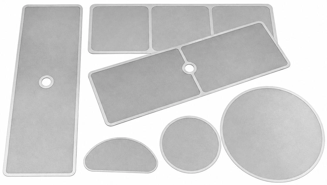
Application and Selection.
Photochemical machining forms the filtration pattern in a thin metal sheet. The alloy, active area, support and inspection criteria belong on the component drawing.
- Openings
- Round holes, elongated slots and custom patterns
- Design variables
- Foil thickness, aperture, pitch and open area
- Component forms
- Circular, profiled and drawing specific
Technical Information
Open a section to view the details, tables and illustrations.
Product Forms & Materials
Precision Openings in Thin Metal Foil
Photo etched film is a perforated metal foil or sheet.
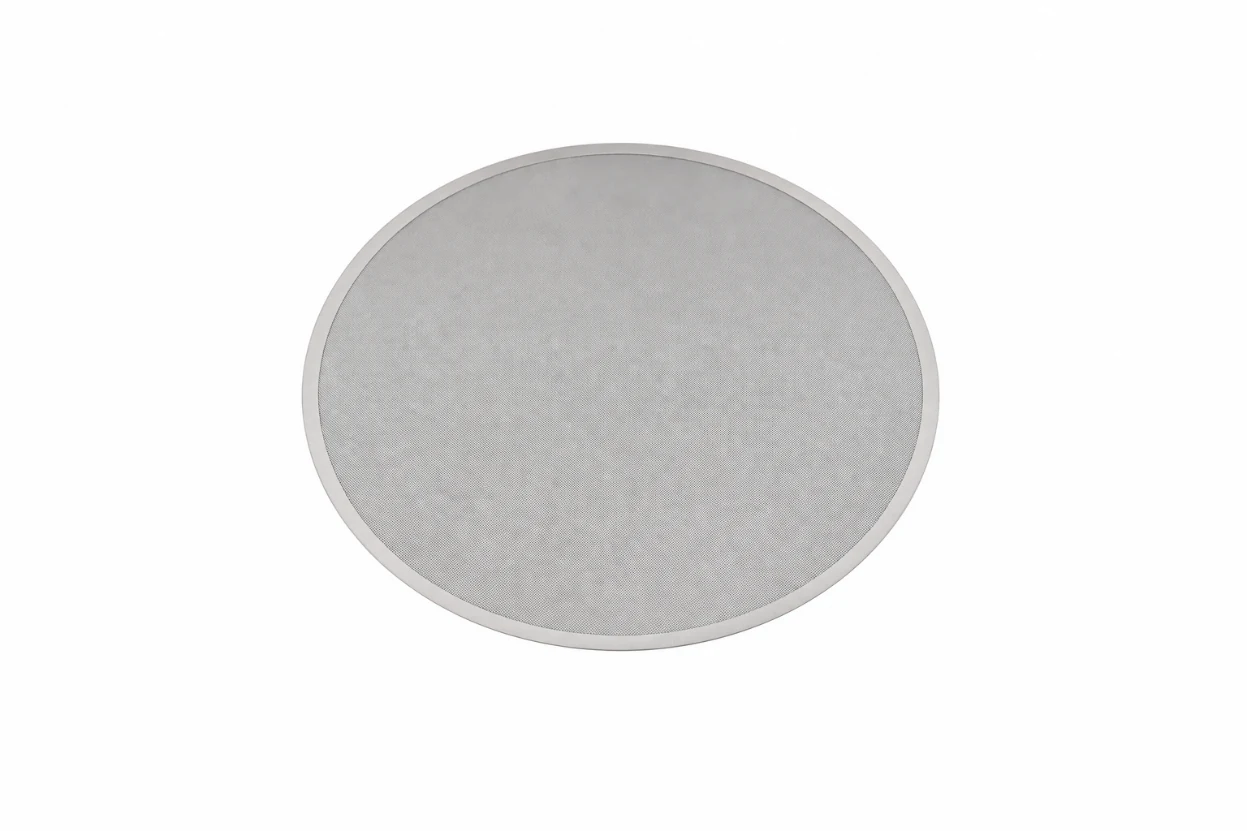
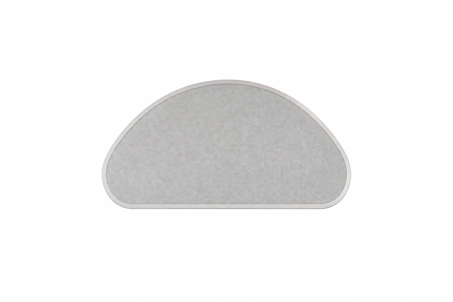
Representative circular and semicircular filter foils
Product Feature | Published Options |
|---|---|
Micropore Patterns | Round holes and elongated, waist shaped holes. |
External Profiles | Circular, semicircular and rectangular; customer defined profiles. |
Materials | Stainless steel, copper, aluminium and other alloy sheets. |
Listed Foil Thickness | 0.05 / 0.08 / 0.10 / 0.12 / 0.15 mm; other sizes by enquiry. |
Product options from the supplier catalogue. Material grade and the selected aperture/thickness combination require confirmation.
Design Freedom
The photo tool defines the opening pattern and component outline. Unperforated margins, support lands and fixing details can be incorporated into the drawing. Digital artwork also allows pattern changes without a dedicated punching die.
Two Separate Design Choices
The external contour locates the part in the assembly; the micro hole pattern performs the filtration. Specify both independently - for example, a circular disc with elongated openings.
Manufacturing Principle & Capability
Photochemical Etching
A light sensitive resist protects selected areas of the metal. After exposure and development, chemical etching removes the exposed metal to form the openings and outer profile.
Prepare the Metal. Select the alloy and thickness, cut the sheet and clean the surface.
Image the Pattern. Apply photoresist, expose the artwork and develop the areas that will be etched.
Etch the Openings. Use a controlled chemical process to remove the unprotected metal.
Finish and Inspect. Strip the remaining resist, clean and dry the part, then inspect it against the drawing.
Published Capability Figures
Parameter | Supplier Reported Value |
|---|---|
Etching Area | 500 × 600 mm |
Material Thickness Range | 0.01 - 2.0 mm |
Thin Sheet Emphasis | Especially suitable below 0.5 mm |
Minimum Hole Feature* | 0.01 - 0.03 mm (10 - 30 µm) |
Minimum “wire diameter”* | 0.01 - 0.03 mm, as worded in the source |
* The catalogue gives these as general capability figures, without a linked material/thickness combination or dimensional tolerance. “Wire diameter” needs clarification for solid foil; specify the residual web/land width on the drawing.
Confirm the Combination
Minimum aperture, remaining web and tolerance depend on foil thickness, alloy and etch profile. The smallest feature value must not be assumed achievable across the entire thickness range.
A stated hole diameter is a dimensional feature, not a demonstrated particle retention efficiency. Confirm the finished opening and the filtration test basis for the intended duty.
Aperture Geometry & Open Area
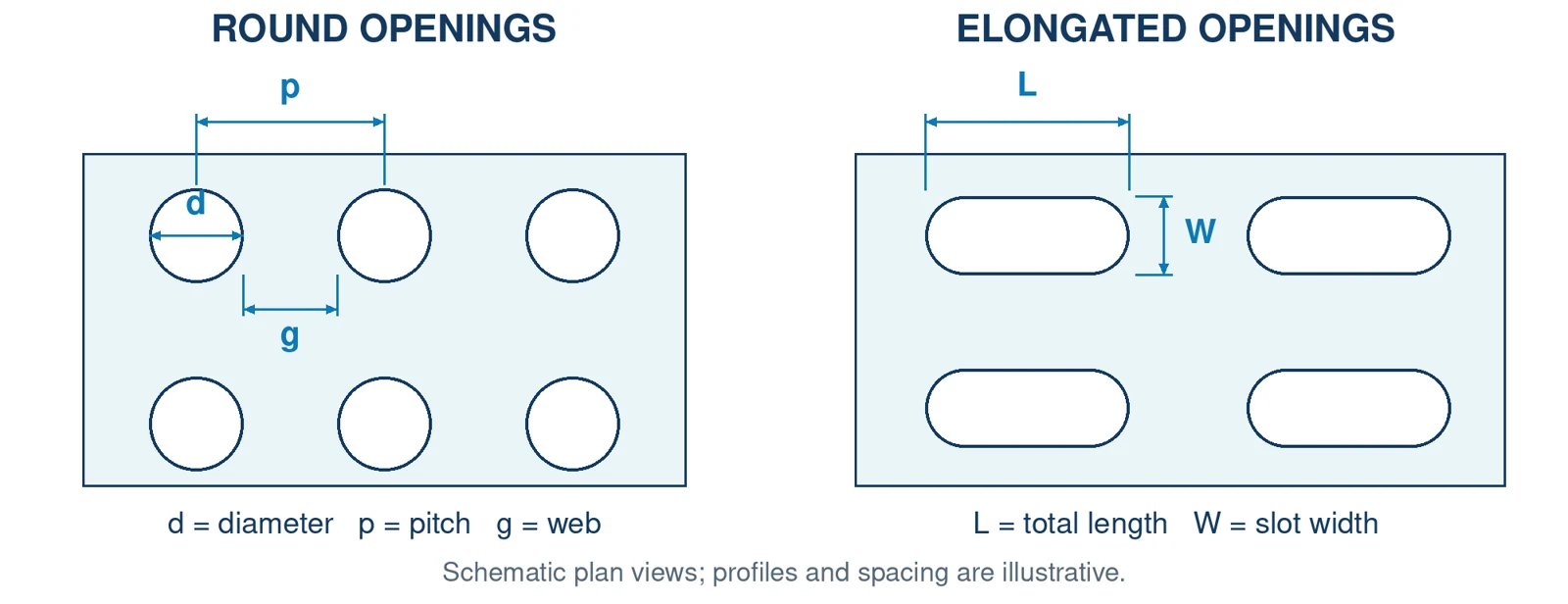
Specify More than Hole Diameter
Opening geometry and the remaining metal web
Round openings. Specify diameter d, centre to centre pitch p, array arrangement and foil thickness. For equal pitch in a square array, the minimum web is g = p − d.
Elongated openings. Specify width W, total length L, end radius, spacing and orientation. Confirm the required particle retention under the actual flow and contamination conditions.
Round Holes on a Square Array
Open Area (%) = 100 × πd² / (4p²)
HOLE d (mm) | PITCH p (mm) | WEB g (mm) | Open Area |
|---|---|---|---|
0.100 | 0.200 | 0.100 | 19.6% |
0.100 | 0.150 | 0.050 | 34.9% |
Calculated examples for an ideal perforated field; solid margins and supports reduce the open area of the complete part. These examples do not confirm manufacturability or pressure loss performance.
Control the through Thickness Profile
Etching removes metal laterally and through its thickness, so openings may taper or form a cusp. Agree the aperture measurement plane and any required installation direction.
A conical or other engineered pore profile is a specific design option; it should be confirmed on the drawing rather than assumed for every etched foil.
Application & Technical Review
Integrate the Foil into the Filter Assembly
Applications include precision screens, filter plates and cartridge media for chemical, petroleum, food and pharmaceutical processing, alongside synthetic filament spinning.
For a spinning application, review the foil within the approved spin pack arrangement, including the upstream media, support components, distribution plate and spinneret. The assembly drawing determines its position and orientation.
Process and Objective. Identify the polymer or fluid grade, contamination concern, current filter reference and the quality improvement sought. Include throughput, viscosity basis and operating temperature.
Mechanical Duty. State operating pressure, maximum differential pressure, pressure cycling and the supported span. Include support details, foil flatness, sealing lands and any clamping features.
Aperture and Drawing. Supply the external contour, active area, thickness, aperture geometry, pitch, tolerances and measurement plane. Identify mounting holes, edge details and the drawing revision.
Material and Cleaning. Confirm the exact alloy grade, cleaning chemistry, temperature and reuse method. Handling, washing and installation must preserve the thin foil and its openings.
Inspection and Supply. Agree aperture sampling, dimensional inspection, surface cleanliness, material documentation and traceability. Include trial quantity, expected consumption and delivery requirement.
Trial Acceptance
Compare initial pressure loss, pressure rise during operation, run duration and downstream quality at matched conditions. For spinning, record spinneret blockage and filament breaks against a defined baseline.
The supplier page does not give a complete pressure, temperature or efficiency rating for a finished filter. These limits depend on the selected material, geometry and supported assembly.
Prepare Your Enquiry
What to Send Us.
Alloy; foil thickness; external profile; hole or slot dimensions; pitch; tolerances; support arrangement; quantity.
Discuss this product